DIY 4th Axis (Rino/Vexta)

Signed-In Members Don't See This Ad

budnder

Member
Joined
Dec 28, 2015
Messages
527
Location
Chicago/Tucson
I've had a CNC for a few years, but haven't used it for anything related to pens, aside from making a jig or two. I decided to take the plunge on a fourth axis (rotary axis). Because my CNC doesn't have a whole lot of Z (up/down), I really needed a fourth axis centered around 45mm (~1.75") above the table – anything much taller and my bit wasn't going to be able to lift high enough to get on top of the stock.

The canned solutions I could find (headstock/rails/tailstock) all seemed to be around 65mm, with maybe the occasional 55mm. So I looked into what it would take to roll my own. And since I was doing my own, I figured I could be a little pickier about the parts – I fancied a low backlash harmonic or geared drive. From my research, something with a gear reduction of 25 – 50 was a good compromise between speed and accuracy. I found these little surplus Rino/Vexta motor/drive combos to be attractive at around $100 on ebay:

4th-axis-drive.jpg

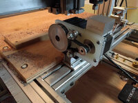
So I watched and waited and snagged one when it popped up for auction. As I was likely going to have to hack a tailstock as well due to the 45mm height, I found one on ebay that had a 70mm height, but was modular, so I could easily remove the riser blocks and base and replace them with my own:

4th-axis-tail.jpg

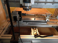
I had to make my own drive shaft for the Rino gear box and put a 3 / 4 16TPI thread on it so it would be compatible with Sherline accessories. I used aluminum because I had some. I built up a mount for the drive and tailstock out of maple, and figured I'd just use the T-tracks already built into my CNC bed as rails.
The gecko 540 driver and Mach3 software I was using on the CNC were already 4th axis capable, so wiring it up was pretty straight forward, with only a little trial and error and the usual googling for help to get things sorted and smoothed over.

The unknown for me in this is if the aluminum drive shaft and wooden mounts will be stiff enough to be accurate. It's a given that this setup will have to be "dialed" in to be square with the tooling every time I take it on and off the table. I figure I'll eventually develop a jig/indicator/macro/process for making this easy and repeatable.

The video shows a little test I did. I didn't futz too much with the squareness of everything, and it didn't seem to matter all that much. I had the rotation running in reverse so it carved out the text backwards (DOH!). I filled the (backwards) text with some ground coffee and CA and then turned it manually just to see how it was going to look, and I'm pretty satisfied. This particular font is a requirement for the first project I'm attempting, but if I had a choice, I'd go with a font that didn't have as many tiny nooks and crannies. I can go a little bigger and that will help. I used an 1/8" end mill to "turn" the blank to shape, and then a tiny R0.25 tapered ball nose engraving bit for the lettering ( https://www.amazon.com/gp/product/B01N7S00BH ). I started with a ¾" round blank with tube already glued in, and roughing it to shape took about 5 minutes. Same for engraving the text. I have a little 3 inch Sherline 4 jaw chuck that I could have used to hold the blank, but decided to use a basic pen turning mandrel instead to see if that would work (seemed fine and simpler to me than the 4 jaw).


All in all I'm pretty happy with this little setup so far. I'm using a combination of Fusion and Vetric Desktop to generate the gcode. I started my first "not a test" cutting tonight...
 
Signed-In Members Don't See This Ad

MRDucks2

Member
Joined
Jul 17, 2017
Messages
3,215
Location
Bristow, IN
Keep us posted. I am trying various options with an X-Carve. Right now I am purely mechanical but seeing the small headstock/servo combos has me thinking.

With the X-carve I would have the option of cutting a hole in the waste board and mounting surface to lower a driven 4th axis, if necessary.


Sent from my iPhone using Penturners.org mobile app
 

budnder

Member
Joined
Dec 28, 2015
Messages
527
Location
Chicago/Tucson
...with the X-carve I would have the option of cutting a hole in the waste board and mounting surface to lower a driven 4th axis, if necessary...

Yeah, I thought quite a bit about hacking up the back 6 inches of my table to get some depth. There's some Y axis plumbing on the side, but I recall the center 18 inches (my table is 24x24) is open, so I could even lower than the spoil board. I've also wanted to have the ability to have stock at an angle, which I could do if I had a void back there. If I'd have found a kit I really liked, I might have looked at it harder.

If I was setting up a new 24 x 24 table, I think I'd design it so that there was a 6" x 18" center back void for appliances/jigs that wanted to interact with the CNC, and the rotary setup could plug into that. Oh well, next time...

I ran my first little project tonight and it took about two hours, but looks exactly like what I wanted. I used an imported bitmap in Vcarve for the design, and I that really took a long time to carve - longer than I think it should given the simplicity of the design. Maybe I should have just drawn it in Vcarve so I could use a different toolpath technique.

The pic shows the engraving design on the back side - there's text on the front. I cast black Liquid Diamonds around it and stuck it in the pressure pot right before I turned out the lights. My plan was to just turn it down to size by hand after I've got it cast in black. The engraving was 30 thousands deep and I modeled the blank to be 10 thousands proud, so I should have a 20 thousands deep engraving when I get it turned. We'll see...

4th-Axis-Casting.jpg
 

MRDucks2

Member
Joined
Jul 17, 2017
Messages
3,215
Location
Bristow, IN
Like the idea with the overcast. Tried something similar with Alumilite Clear regular and had separation near the the ends when I got too thin, but I was turning it off on the lathe.

I have the 1000mm x 1000mm X-Carve so, like you have plenty of room in the back corners. Right now developing the jig just for laser, which is easier since there is not load on the workpiece.

Routing will be your approach helps me, obviously.


Sent from my iPhone using Penturners.org mobile app
 

budnder

Member
Joined
Dec 28, 2015
Messages
527
Location
Chicago/Tucson
Well, the next two attempts were interesting. The Liquid Diamonds still is like thick tar after two days, so I don't think that's ever going to set. Either it was too old (18+months) or I put too much solid into it to make it black.

So I tried another blank, taking the opportunity to dial in the accuracy of my axis. For some reason, my Z was too low, so when the CNC roughed out the pen, it was already at or a hair below the finished diameter. For grins, I went ahead and engraved it, though the engraving was much thinner than I had planned. I packed it quickly with coffee and CA and turned it down. Yup, the engraving turned off here and there.

I think next time for my Z height, I'm going to start high, make a roughing pass, measure the diameter, and then dial it lower until I get what I want for a roughing diameter. E.g. cut, measure, observe, adjust vs. trying to calculate it by touching off the mandrel.

I'm kinda liking the retro look of that dark brown coffee on the cherry, though. I think maybe I might just do that instead of attempting a black casting fill.

macpen3-9277.jpg
 

smik

Member
Joined
Apr 12, 2013
Messages
234
Location
Ohio
Well, the next two attempts were interesting. The Liquid Diamonds still is like thick tar after two days, so I don't think that's ever going to set. Either it was too old (18+months) or I put too much solid into it to make it black.

So I tried another blank, taking the opportunity to dial in the accuracy of my axis. For some reason, my Z was too low, so when the CNC roughed out the pen, it was already at or a hair below the finished diameter. For grins, I went ahead and engraved it, though the engraving was much thinner than I had planned. I packed it quickly with coffee and CA and turned it down. Yup, the engraving turned off here and there.

I think next time for my Z height, I'm going to start high, make a roughing pass, measure the diameter, and then dial it lower until I get what I want for a roughing diameter. E.g. cut, measure, observe, adjust vs. trying to calculate it by touching off the mandrel.

I'm kinda liking the retro look of that dark brown coffee on the cherry, though. I think maybe I might just do that instead of attempting a black casting fill.

View attachment 225771
That color combo does look very good. I have similar issues with z- axis varying. Machine tolerance is rated at +-.005 with .002 repeatabily. Hows your concentricity look, once in awhile a piece will go noticeably off. I either overtightened mandrel, didnt have perpendicular sides or didnt clean out the brass tube well enough.
 

budnder

Member
Joined
Dec 28, 2015
Messages
527
Location
Chicago/Tucson
You make a good point regarding the accuracy of these CNC's. I don't know what mine is, but it's certainly not perfect.

I definitely saw some concentricity issues in the blanks when I took them off the CNC. I suspected it had to do with my work holding, rather than the axis. I was using some internal spacer/bushings as I was afraid to use the metal bushings since I'm carving all the way to the end. Now that I've got some experience, I trust that I can keep my end carving up higher than the bushings and double check the tool path by touching off the bushings before I carve. I'll use the regular bushings for my next attempt.

To verify, I put indicators on everything I could think of:


At the drive shaft, I'm 0.003 off, which seems fine to me. Somehow, amazingly, the inside of the bushing on the mandrel is only 0.001 off... not sure how to explain that being better than the shaft - maybe it has to do with load/tension. Measuring the parallelness of the mandrel, I was 0.012 low on the tailstock end, so I shimmed the tailstock up a bit, and that dropped down to 0.005, which seems close enough for me given that it's across the entire length of the shaft.
 

smik

Member
Joined
Apr 12, 2013
Messages
234
Location
Ohio
You make a good point regarding the accuracy of these CNC's. I don't know what mine is, but it's certainly not perfect.

I definitely saw some concentricity issues in the blanks when I took them off the CNC. I suspected it had to do with my work holding, rather than the axis. I was using some internal spacer/bushings as I was afraid to use the metal bushings since I'm carving all the way to the end. Now that I've got some experience, I trust that I can keep my end carving up higher than the bushings and double check the tool path by touching off the bushings before I carve. I'll use the regular bushings for my next attempt.

To verify, I put indicators on everything I could think of:


At the drive shaft, I'm 0.003 off, which seems fine to me. Somehow, amazingly, the inside of the bushing on the mandrel is only 0.001 off... not sure how to explain that being better than the shaft - maybe it has to do with load/tension. Measuring the parallelness of the mandrel, I was 0.012 low on the tailstock end, so I shimmed the tailstock up a bit, and that dropped down to 0.005, which seems close enough for me given that it's across the entire length of the shaft.
I try to keep the mandrel .002 or better. I usually check each time I change mandrel but was experimenting a design and didnt. I had .005 taper from collet to tailstock end. I adjusted tailstock and got everything to .002 or better. I turn the bushings below my finish dia. by about .010-.015.
I'm going to experiment with an id expansion arbor, I'd like to eliminate the mandrel and bushings.
 

budnder

Member
Joined
Dec 28, 2015
Messages
527
Location
Chicago/Tucson
Well, I finally got a keeper, although I had a little unrelated issue in assembly that'll mean I'll just keep this one for myself.

After the rough profile pass on the CNC I measured my diameter while it was still mounted, and I was 0.003" to thick on the headstock end, and 0.003" to thin on the tailstock side. That should be within the tolerances of my design, so I proceeded. By the way, here was my design:

Design.jpg


The engraving part on the CNC was uneventful, better than before actually, because I had adjusted the specs on my 1/16" clearing bit - I measured the bit, and it's only 0.058", so was over stepping too much before.

After I unmounted it from the lathe, I measured the concentricity. I was good on my headstock end, but 0.008 out of round on the tailstock end. It visually looked ok to me, but I could repeatedly measure a difference. Again, within my design tolerances in theory, so I proceed.

While I like the look of the coffee fill, it's kind of a nasty process. I tried mixing the CA and coffee in a dixie cup, but it sets way to fast with both thick and thin ca. The only way I could do it, was to pack dry coffee on the pen and then drip CA on it. The CA has a tendency to want to run over the top of the coffee, rather than soak in, so it's a messy process.

Here's a couple of quick looks along the way:


For my next attempt, I'm going to put the indicator on the tailstock bushing and see if I can figure out where my apparent wobble is.
 

budnder

Member
Joined
Dec 28, 2015
Messages
527
Location
Chicago/Tucson
After a few experiments with mandrels and not great success, I settled on sort of a "between centers" hybrid. I turned a couple of bushings where the business end is your standard 0.247"-ish diameter so my regular pen bushing goes over it. The other end, I just faced the 1/2" stock, so it's probably 0.48" in diameter or so. On the fat end, I center drilled a 60 degree divot for a live center to snuggle into.

20190927_101533.jpg


At the headstock, I'm holding the fat end in an independent 4 jaw, so was able to get the runout dialed down to 0.001". At the tailstock end, the runout was a little higher, 0.003" or so. I have a collet chuck on order for this, so figure that'll be a more convenient ongoing holder for my TBC bushing rather than the 4 jaw.

What I don't know for certain yet, is if I'll have issues with work "slippage"... I'm relying on the tailstock pressure and the precision of the fit to hold things together. It feels good and tight when I try and make it slip with my hand, so I think it'll work.

Here's what it looks like all assembled:


20190927_114653.jpg


That CD peaking out from under the tailstock was my idea of a 0.050" shim... :)
 

smik

Member
Joined
Apr 12, 2013
Messages
234
Location
Ohio
After a few experiments with mandrels and not great success, I settled on sort of a "between centers" hybrid. I turned a couple of bushings where the business end is your standard 0.247"-ish diameter so my regular pen bushing goes over it. The other end, I just faced the 1/2" stock, so it's probably 0.48" in diameter or so. On the fat end, I center drilled a 60 degree divot for a live center to snuggle into.

View attachment 225944

At the headstock, I'm holding the fat end in an independent 4 jaw, so was able to get the runout dialed down to 0.001". At the tailstock end, the runout was a little higher, 0.003" or so. I have a collet chuck on order for this, so figure that'll be a more convenient ongoing holder for my TBC bushing rather than the 4 jaw.

What I don't know for certain yet, is if I'll have issues with work "slippage"... I'm relying on the tailstock pressure and the precision of the fit to hold things together. It feels good and tight when I try and make it slip with my hand, so I think it'll work.

Here's what it looks like all assembled:


View attachment 225945

That CD peaking out from under the tailstock was my idea of a 0.050" shim... :)
Nice setup. I like the cd shim, paper works good for that additional fine tuning. I dont see you having an issue with slipping. If you do I have an idea.
 
Top Bottom