
Wmcullen
Member
I'm not sure if this process is right or wrong; unique or common. But it works for me and I want to share in case it's interesting. |
12: Improved Eccentric Ring
last post: 11: Eccentric Revolution


The key thing to remember is: if there's a stripe of wood in the blank, its angle will be a constant.
And two holes drilled straight into the blank will have a varying angle based on the diameter.
Solution #2
In addition to the angle of the ring of dots (45-degrees), I need to declare the final pen thickness before making my jig.
I decided on a pen that's 0.5" in diameter.

Problem #3: Centering Holes in Segment
I have a blank with a 45-degree stripe in it and a jig to drill holes. How do I place my jig if I haven't turned to my final diameter and the stripe could still move?
Solution #3
This took me a couple of cycles to figure out!
Start drilling on the side at either the 3 o'clock or 9 o'clock position.
Only at these two points will the center remain constant: independent of the diameter of the blank.

Problem #4
How do you find the 3 o'clock or 9 o'clock position? With style!
Solution #4
Here's my approach:
1. On the lathe, mark in pencil both high and low points of the stripe.
2. Using calipers find the midpoint and draw a bisecting line.
While the high and low points will move as the piece is turned, the middle will remain the middle.
3. Again, using calipers, find the place along this bisecting line where there is an equal amount of dark wood above and below.
4. No matter how far down you turn the piece this spot should remain in the center of the stripe at this angle.
5. Using the new Eccentric Jig, begin drilling in the 3 (or 9) o'clock position and work your way around.


Carefully turn the piece until it is exactly 0.5" in diameter. At that size the dots should rest squarely in the center of the stripe.

Summary
This was a great challenge that improved my original jig design and helped me wrap my head around some interesting facts about turning segmented blanks.
Thanks for reading!
Cullen
Post Note; Why didn't you....
The Challenge, as I decided to interpret it included:
1. dots appear in off-axis ring
2. dots are inside a stripe
3. dots are centered in the stripe
4. dots appear round, not oval
5. pen blank is not turned to final dimension before drilling dot holes
I've sketched about a dozen ways to accomplish pens that address most of these challenges, and a couple of ways that accomplish them all.
In my estimation, this is the simplest way to do it given my equipment. It also allows for the fewest "points of probable failure."
Jig Notes
The attached file is called: Revolution45at0.5inches.obj
This jig is offered "as-is" for anyone who wants to play with it. If I make modifications I will continue to post.
If you need previous jigs, you can find them in the respective posts at:
Post about jig with link to downloadable 3D print file.
Post about the first jig attachment for angled hole drilling.
The attached zip file contains an *.obj geometry file with the pieces pictured below.
If You Print The Jig
You will need to glue
 a few parts together:
Ring Attachment (shown in blue)
Guide (in purple)


last post: 11: Eccentric Revolution
A couple of weeks ago Ken asked if the "homebrew" jig I've been writing about could put an angled ring of dots in the center of a segmented band. I was already thinking about adding an attachment for angled drilling, so the question thrilled me. But it quickly became clear my latest design was not up for that job... and frankly I wasn't thinking through the problem clearly enough. I had to tinker before I figured it out. Here's the result:

The Problems
My last jig attachment didn't produce a true eccentricity; and I misunderstood how dots would interact with an angled stripe. I came up with solutions and am excited to share what I found.
Background & Overview
I've written a few posts on the evolution of this 3D printed jig that clamps to my drill press. In a nutshell a roughed blank is held in place and rotates at set angles with the help of a guide.
As always, I'm happy to share this new 3d printable file. More info on all jigs at end of the post.

Before I break down how I got the dots centered in the stripe, here's a quick overview of the whole process.

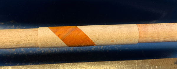
Using a compound miter saw I made a row of curly maple blanks with a 45-degree stripe of dark wood (padauk).
The blank was turned a bit larger than the final pen diameter.
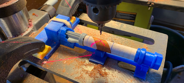
Holes were drilled using my new custom 3D printed jig attachment.

Dowels were glued and the pen was turned to its final dimension and finished.

If you think you see an easy way to accomplish Ken's challenge you could be absolutely right.
Personally, I thought it seemed easy before giving it more consideration.
Let's dive into it.
Problem #1: Sine waves
My last jig's steps were spaced at constant distances. I assumed that would create an eccentric circle. It doesn't.
In fact, when I saw the pattern this jig made I remember thinking at the time, "Boy the top of that curve looks pretty sharp.... more like a V than a U."
Solution #1
I modeled the ring in 3D and saw the holes appeared where I expected only every 90 degrees and traveled in a curve elsewhere.
Hmmmm... looked like a sine wave. Time to dust off my 10th-grade math and figure out better step distances for the jig.


The Good news: This new jig attachment produced a ring of dots at a 45-degree angle to match the stripe of wood.
The Bad news: The ring will only measure 45-degrees at a specific pen diameter. Whaaaaaat? Read on.
Problem #2: Shifting Angle
The angle of the ring of dots will change based on the diameter of the pen. This took a moment to wrap my head around until I made this picture.

If I drill two holes (yellow) into a blank on opposite sides, I can determine the angle between them.
But if the diameter (height) changes the angle changes.
If my lathe magically added wood, the 45-degree angle would approach a vertical line.
If I turn the wood smaller, that angle approaches horizontal.
The Problems
My last jig attachment didn't produce a true eccentricity; and I misunderstood how dots would interact with an angled stripe. I came up with solutions and am excited to share what I found.
Background & Overview
I've written a few posts on the evolution of this 3D printed jig that clamps to my drill press. In a nutshell a roughed blank is held in place and rotates at set angles with the help of a guide.
As always, I'm happy to share this new 3d printable file. More info on all jigs at end of the post.
Before I break down how I got the dots centered in the stripe, here's a quick overview of the whole process.
Using a compound miter saw I made a row of curly maple blanks with a 45-degree stripe of dark wood (padauk).
The blank was turned a bit larger than the final pen diameter.
Holes were drilled using my new custom 3D printed jig attachment.
Dowels were glued and the pen was turned to its final dimension and finished.
If you think you see an easy way to accomplish Ken's challenge you could be absolutely right.
Personally, I thought it seemed easy before giving it more consideration.
Let's dive into it.
Problem #1: Sine waves
My last jig's steps were spaced at constant distances. I assumed that would create an eccentric circle. It doesn't.
In fact, when I saw the pattern this jig made I remember thinking at the time, "Boy the top of that curve looks pretty sharp.... more like a V than a U."
Solution #1
I modeled the ring in 3D and saw the holes appeared where I expected only every 90 degrees and traveled in a curve elsewhere.
Hmmmm... looked like a sine wave. Time to dust off my 10th-grade math and figure out better step distances for the jig.
The Good news: This new jig attachment produced a ring of dots at a 45-degree angle to match the stripe of wood.
The Bad news: The ring will only measure 45-degrees at a specific pen diameter. Whaaaaaat? Read on.
Problem #2: Shifting Angle
The angle of the ring of dots will change based on the diameter of the pen. This took a moment to wrap my head around until I made this picture.
If I drill two holes (yellow) into a blank on opposite sides, I can determine the angle between them.
But if the diameter (height) changes the angle changes.
If my lathe magically added wood, the 45-degree angle would approach a vertical line.
If I turn the wood smaller, that angle approaches horizontal.
Aside
Now it would greatly simplify things if we drilled the holes at an angle.
But that would produce ovals instead of circles.
Circles are my objective.
The key thing to remember is: if there's a stripe of wood in the blank, its angle will be a constant.
And two holes drilled straight into the blank will have a varying angle based on the diameter.
Solution #2
In addition to the angle of the ring of dots (45-degrees), I need to declare the final pen thickness before making my jig.
I decided on a pen that's 0.5" in diameter.
Process Decision
You may disagree with this, and I could be wrong, but I think I'll get a much better final product if I drill and glue my blank before turning it down to its final dimensions. However, this creates another little problem.
Problem #3: Centering Holes in Segment
I have a blank with a 45-degree stripe in it and a jig to drill holes. How do I place my jig if I haven't turned to my final diameter and the stripe could still move?
Solution #3
This took me a couple of cycles to figure out!
Start drilling on the side at either the 3 o'clock or 9 o'clock position.
Only at these two points will the center remain constant: independent of the diameter of the blank.
Problem #4
How do you find the 3 o'clock or 9 o'clock position? With style!
Solution #4
Here's my approach:
1. On the lathe, mark in pencil both high and low points of the stripe.
2. Using calipers find the midpoint and draw a bisecting line.
While the high and low points will move as the piece is turned, the middle will remain the middle.
3. Again, using calipers, find the place along this bisecting line where there is an equal amount of dark wood above and below.
4. No matter how far down you turn the piece this spot should remain in the center of the stripe at this angle.
5. Using the new Eccentric Jig, begin drilling in the 3 (or 9) o'clock position and work your way around.
Carefully turn the piece until it is exactly 0.5" in diameter. At that size the dots should rest squarely in the center of the stripe.
Summary
This was a great challenge that improved my original jig design and helped me wrap my head around some interesting facts about turning segmented blanks.
Thanks for reading!
Cullen
Post Note; Why didn't you....
The Challenge, as I decided to interpret it included:
1. dots appear in off-axis ring
2. dots are inside a stripe
3. dots are centered in the stripe
4. dots appear round, not oval
5. pen blank is not turned to final dimension before drilling dot holes
I've sketched about a dozen ways to accomplish pens that address most of these challenges, and a couple of ways that accomplish them all.
In my estimation, this is the simplest way to do it given my equipment. It also allows for the fewest "points of probable failure."
Jig Notes
The attached file is called: Revolution45at0.5inches.obj
This jig is offered "as-is" for anyone who wants to play with it. If I make modifications I will continue to post.
If you need previous jigs, you can find them in the respective posts at:
Post about jig with link to downloadable 3D print file.
Post about the first jig attachment for angled hole drilling.
The attached zip file contains an *.obj geometry file with the pieces pictured below.
If You Print The Jig
You will need to glue
Ring Attachment (shown in blue)
Guide (in purple)


")