
This is my first post here – hopefully it will be noteworthy. I recently purchased my first fountain pen, a Charcoal Lamy Safari with a Fine nib. I decided that I wanted a second, possibly a third, etc.
I also decided that I wanted to make it myself – so I came here and started reading. This is the end result. I thought I would try to document everything I did and more importantly the thought process and reasoning behind why I did it – in case it could possibly benefit anyone else.
*******
I wanted to make as much of the pen myself. And since I really only planned on making myself a pen, I didn't want to spend an arm and a leg on custom tooling. Luckily for me, I have a fairly well outfitted machine shop in the basement so I set out to make everything I needed.
So I purchased some acrylic blanks from ExoticBlanks and added on some of the replacement Edison nibs with an order I placed at gouletpens. I initially thought about casting my own blanks from the outset but decided I didn't want to get too carried away.
And then the work began.
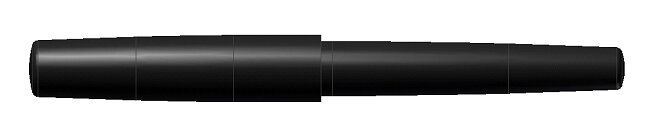
A little background about myself… I am a mechanical engineer with a little bit of machinist, welder, woodworker, and auto-mechanic thrown in there for good measure. I set out to draw what I wanted in CAD first. This is more or less what I came up with.
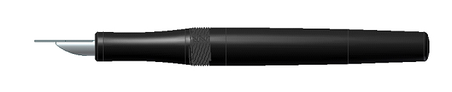

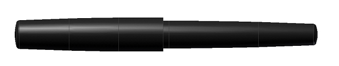
This was designed more or less without a clip in mind. That's only because I haven't figured out quite how I wanted to make one yet.
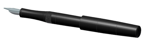
So my first design is a clipless version that is postable. I notice that many of the fountain pens that I've seen here and elsewhere have fairly short sections with the cap threads very close to where the pen is held. Though I haven't personally held many of these designs, I suspect that for most of these, I would find that uncomfortable. I tend to like a longer grip section. That is what drove most of the design of the pen.
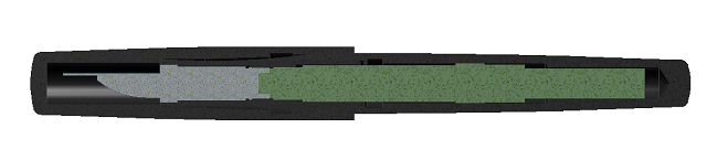
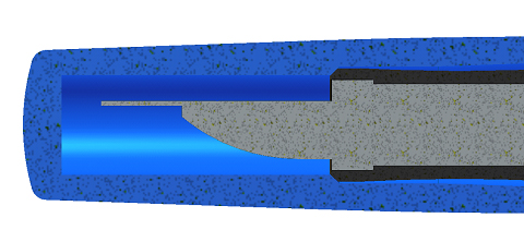
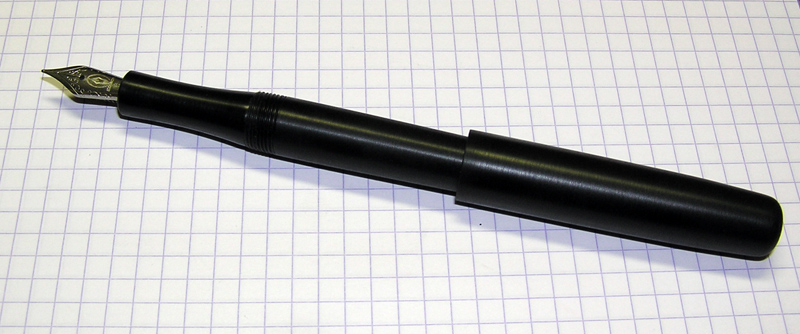
For posting, there is a tapered section inside the cap that mates with a matching taper on at the rear of the pen.
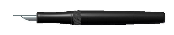
I noticed while examining my Lamy Safari that inside the cap, there is a little rubber collet inside the cap that creates a seal just around the nib. I presume that feature is to prevent the nib from drying out between uses. I incorporated a similar feature in this pen, where the cap bottoms out against a chamfer on the front of the section. That should create a more or less air tight seal and to my mind, should provide the same functionality as some of the commercial features that I've seen. Time will tell I suppose.
[FONT="]So, up until this point, everything pretty much existed only on the computer screen. It was time to change that. First things first – there's obviously a bit of tooling that I'd need before I could make the actual pen. The #5 nib I was using was an M6.4x0.5mm thread. Not, shall we say, a common size (at least not in my world). I wasn't sure which size I wanted to start out with, so I also acquired a #6 nib. The #6 used an M7.4x0.5mm thread – though the major diameter measured closer to 7.2mm.
[/FONT]
The above image shows one of the #5 nib assemblies. One of the other things that I did, which I forgot to take pictures of, was that I trimmed away the material on the feed holder outside the dashed red lines to get rid of the raised lip at the front. To do that, I chucked the feed holder in the closest ER 32 collet in a hex collet block. Then I mounted the hex collet block on the 3-jaw in the lathe and turned it down with a very sharp tool. I did this because I wanted the feed holder to sit flush in a the counterbore at the front of the section.
As it so happens, a couple of years ago I acquired the metric change gears for my south bend 10k lathe, so I was in business. The first thing I set out to do was to make a hub with threads that fit the feed holders. The reason was to have a guage of sorts for the subsequent creation of a tap. The only problem was that I didn't have any internal threading tools that could fit through diameters that small. So, the actual first task was to make a tool to make a gauge to make a tap. Right..


After that, I used the internal threading tool to single point a female thread for each of the two feeds in a couple pieces of aluminum.


After this was complete, I started to make the two custom taps, using the aluminum hubs as a reference. The stock that I used was a spare grade 8 bolt that was left over from a previous project. The first step is basically to make a bolt with the appropriate thread form. I started by turning the major diameter, then cut the taper at the front, then cut the threads with a single point thread cutting tool.


Once I had a bolt that was just able to thread into aluminum hub, the next step was to cut the flutes. I did this using my milling machine with the help of an ER32 square collet block. There are a number of ways to make flutes. I happened to have a ball end mill of an appropriate size, so I used that. No matter how you go about doing it, the goal is to make sure that the cutting edge has some rake to it. When using a ball end mill, the easiest way to insure that you have a positive rake at the cutting edge is to cut with the end mill slightly off center. I've included a sketch to show how this is achieved.


Immediately after I had cut the flutes, the tap was in a virtually unusable state, 75% of the threads had a huge burr, thanks to the end mill. Note: most professionally made taps are ground, not machined and thus don't fall victim to this. So I used a small wire wheel on the dremel to remove the burrs. Tedious, but necessary. I also used the square collet block to machine the square flats in the driving end.


If I had been in need of cutting a thread into steel, I would have used a material that was hardenable. I had some 5/8" W1 tool steel (drill rod) around, but it wasn't worth the hassle to use for this much smaller diameter. As far as I know, the material used in grade 8 hardware is already quenched to achieve the 130 ksi yield strength they are spec'ed at. So heating this material up and quenching probably wouldn't achieve any increase in hardness. Since I only intend to use this on plastics, it wasn't really necessary to do anything further anyway.

I repeated the operation for a second tap that would fit the threads on the #6 feed holder.

[FONT="]I tested the taps on a couple of piece of scraps of delrin and was very pleased with the fit.
[/FONT]

Ok. The next gaps in tooling were for the section-to-body threads and the cap-to-body threads. After going through the design process for this first pen, using the #5 nib, I can definitely see how all the dimensions of the pen are driven by the dimensions of the feed. In my job, I tend to work with highly stressed metal components – so designing a pen with areas that have wall thickness on the order of ~0.030" thick makes me a bit squeamish.
As a bit of a sanity check, I measured the wall thickness of the Lamy Safari in a couple of places. Sure enough, the pen I have been carrying faithfully in my jeans pants pocket has what seems like a miniscule wall thickness between the section and the body – yet in the month or so that I've been carrying it I haven't broken it yet. I'll cross my fingers..
Now for the pen body-to-cap joint. Here, I wanted to use a triple start thread. This was mostly driven by the desire to minimize the number of turns to take the cap off during use. But there was also a small part of me that wanted to do it because I've never done it before – and I like challenging myself. I have kind of been intrigued with multi-start threads ever since I first learned about them in college while talking with one of the machinists I used to work with.
I decided on an M12x0.8mmx2.4L thread (major diameter = 12 mm, pitch = 0.8mm, lead = 2.4mm). So, custom triple start thread, here goes nothing..
I started with the male tap as that seemed the easiest place to begin. I again single pointed this thread, although there was a bit more complexity with this being a triple start thread. Here, I turned between centers. That is to say, that I drilled a 60 degree center in either end of the tap. In the three jaw chuck, I mounted a piece of steel and turned a 60 degree center in place. This insures that the center is aligned with the headstock axis. I then mounted the tap between the dead-center in the chuck and a live-center in the tail stock. A simple, custom dog was made to drive the tap using the chuck jaws.


A triple start thread is nothing more than three individual threads separated by 120 degrees. With the tap mounted between centers, to cut the three threads in sync all I needed to do was change which jaw the dog was driven by. The tailstock could be loosened and the tap repositioned with a high degree of accuracy. It should be noted that this procedure can only be used for external threads. A different method must be used for internal threads as you can't very well support the part using the tailstock if you have to cut on the ID.
So, by the end of this procedure, I had another bolt which had the appropriate threadform. Since I didn't have a reference part to check the fit of the thread, I kind of winged the thread depth – when the proportions of the thread looked appropriate, I stopped.

I cut the flutes in this part, except this time, I only cut three flutes instead of four. No real reason for it, just on a whim. I didn't take the flutes back the whole way, in part because I was only making three flutes. With only three flutes, you can't use a caliper or micrometer to measure across the threads to check the size of anything – so I left a full diameter section for the sake of measuring the thread form later on if I should desire.
This full diameter section of thread turned out to be useful later when adjusting the split-adjustable die. (There's a picture that shows the final geometry of the tap after the discussion of the mating die).
As I mentioned already, I couldn't support the die on centers so I needed an alternative way of indexing the die while cutting the female thread. There may be other options for indexing, but the only one that I was readily familiar with was using the compound in-line with the lathe axis to shift the cutting tool over by a distance equal to the pitch. This way, I could cut one of the threads, index the cutting tool using the compound, and then cut the remaining threads. This worked out quite well and I found it to be faster than using the centers.
The difficult part about making the die (and internal threads in general) is that there's no good way to measure where you're at. Technically, you could make a casting of the threads and then extract it and measure off the casting. But that sounds like a lot of work, especially since it would have to be done while the part was still on the lathe to be at all useful.
When I started to go about making the die, there was one aspect of the process that I had not thought of in advance. Though my procedure up until this point had been no different than simply making a custom nut/bolt – there was a subtlety to it that I had neglected. In order to figure out when to stop I had just assumed that I would stop when the tap fit through the die. But as the thread form was starting to look finished, the tap (still was a full screw at this point) still wouldn't fit. I was left scratching my head.
Fed up that things did not appear to be going smoothly, I decided to let it sit until the next morning. Thankfully, I walked away before I did something rash and wasted all my effort up to that point.
Upon thinking about the problem further, I realized the subtle thing that I had been missing. If the tap and die fit together perfectly, the threads that they cut would (in theory) also fit together perfectly. But if there is any looseness in the fit of the tap/die, the threads that they cut would have interference. So necessarily, when making the die – I couldn't use the tap to check the fit. By the time that it fit, the die would be too large (slightly).
That still left me with a dilemma. When to stop removing material? I decided to guess. I took another couple passes until the thread form looked just about right when using my loupe. I kept going until I said to myself, "Just one more pass."
Aside: I have a rule that I try to follow. I think I read about this somewhere specifically with regard to painting. But I find that it's applicable to many situations. Any time that I say to myself, "Just one more…", I stop there. I find that usually by the time I say "just one more" I'm already 95% of the way finished with whatever I was doing. Usually there's some risk involved in going too far and it may well be better off to stop at 95% than try to get that last little bit without going over.
So I stopped when the internal thread in the die looked about right. I took it off the lathe, went over to the mill and used a stub length drill bit to create the cutting edges. Cleaning out the burrs from this process was quite a bit more tedious than for the tap as I had to do each tooth manually.
Unfortunately, it was only after I was looking through pictures after the project was complete that I realized I neglected to take any pictures of the die threading operation while everything was still on the lathe. Oops..


Twenty minutes later, I had something that looked rather like a regular solid 1" die. I chucked up a piece of delrin, turned it so that it had a 12mm major diameter and used the die to cut a thread. And you know what? It was awful. Absolutely terrible. The thread was torn, rough, and all around pretty crappy.
So I tried it again, but this time I reduced the major diameter by a bit. And this one was better. Still terrible, but somewhat less terrible than the first one. So I realized that the die was just a bit too small as it was displacing way too much material. I thought maybe I would have gotten lucky and my "looks just about right" would have resulted in exactly the perfect fit I wanted. Not so.
[FONT="]So I set about turning the then solid die into a split-adjustable die. I drilled and tapped the die for an 8-32 set screw and then used a slitting saw to segment one side of the die. Here the threads are on the entry side. So as you thread the setscrew in, it bears against the other side of the die, causing it to spring open.
[/FONT]
I shortened an 8-32 set screw in the lathe and turned a reduced diameter section to pass through the threads. This worked like a charm.
It was at this point that I realized why all of the other split dies I had measured were on the order of 0.990". I had left the material at the original 1" diameter and when I applied the set screw to slightly expand the die, it no longer fit into my 1" die hold. D'oh. It's the little oversights sometimes that make me laugh. Easily fixed however.
To set the size of the die, I used the full thread portion I had left on my tap. I opened the die until it would just thread over the tap. Then I loosened the screw slightly to relax the die so that it would cut a thread with a hint of clearance. In the end I was able to make what I feel is a very pleasing fit between the mating threads.

Having two parts fit together perfectly knowing that I was responsible for every part of the process was quite satisfying. After completing this part of the project, I can definitely see why quality taps and more specifically dies are so pricey. It's a good thing that my time is "free."
A macro look at one of the split adjustable dies…


The next thing was to repeat the process for the section-to-body threads. Here, I decided to go with a 3/8"-36tpi – 12tpi lead triple start thread. That diameter worked better in my design than the more commonly used 10mm. Mostly was an arbitrary decision.
[FONT="]I won't repeat the description of the process as it was predominantly the same as the one I already described. The only thing I'll mention is my reasoning for going with an English thread as opposed to the more typical M10 at this size range. The reason was twofold. First, I wanted to put the gearing on the lathe back to its original state. The metric change gears that I purchased are not of the same quality as the stock gearing. One of the gears has a bit of a loose fit on the hub that it rides on and ultimately this introduces noise into the gear train which I find annoying. Second and probably more importantly, when using the metric change gears, in order to cut a thread you can't disengage the half-nuts. So you take one pass, then you have to reverse the lathe to move the cutting tool to its original position, lest you lose the timing with the lead screw. Cutting standard (English) threads is much easier because you can disengage the half-nuts and using the thread dial to get the timing correct. It makes for a much faster threading operation and less start/stops on the motor.
[/FONT]

Once I had cleaned all the burrs and crap out of the threads in the various taps I made, I used a cylindrical stone bit mounted in the dremel to sharpen up the flutes. The bits that I used are advertised as being "chain saw sharpening stones." Seemed to work quite well. I also used this to sharpen the inside "flutes" of the dies.

The last bit of tooling (or so I thought) that I required was something to aid in the machining of the inside of the cap. There were some fairly specific features that required close control on the tolerances in order for the cap to work the way I had intended. Here I made what is called a D-bit reamer. In this application, it amounts to a single flute form cutting tool.
The process is as follows: First, you cut the male version of what the finished bore should look like. It's much easier to control the dimensions of outside diameter (since they are so easily measured). Then you machine away almost half of it. The goal is to cut about 0.005" above center – this is important (from what I've read). Cutting more than half way would result in the tool cutting smaller than it should. Cutting it slightly above center gives you some extra material left for sharpening.
I left a full diameter section at both ends. The one at the right would later be machined away, but it provided a second hold down point once mounted at the milling machine.


Some relevant background info on d-bit reamers that I found while I was doing some research for this project…
Why are these called d-bit? If you look at the tool from the front, the cross section looks like a D with half of the diameter removed. Simple as that.
While I used this technique to create a form tool, that doesn't have to be the case. You could just as easily start with a right circular cylinder of the correct diameter, cut the D-shape, sharpen, and voila – you have a custom sized drill bit/reamer. Handy in a pinch if you don't have the time to wait for a specialty tool. Diagram shown below.

In operation, you would begin by creating a starter hole using a drill bit the next fractional size smaller than whatever your reamer is. Then, for the most accurate hole you would using a boring tool to create the exact size you want to a depth of 1-2 times the diameter. This will provide a good starting point (in terms of straightness) for the reamer and will enable it to follow that surface along the length of the whole. Because the d-bit reamer was cut on-size, it more or less acts like it's own pilot surface – but it needs help at the entry to the hole.
This technique is used quite often for machining custom chambers by the gunsmithing community. If you're interested google "d-bit chamber reamer" or just "chamber reamer."
Regarding the use of this technique in other applications and for different materials: If you were going to use a d-bit reamer to cut metal (steel, aluminum, etc), you would need to heat treat it in order to harden the cutting edge. Also, while cutting metals, go slow and use lots of cutting fluid.
The order of operations between cutting away half the body and hardening depends on the intended accuracy of what you're trying to do. If you wanted the utmost accuracy out of the end product, you would harden the reamer first and then remove half the body. The difficulty is that you would then need to grind away all that material, since you've just hardened the whole thing. The result however is that because you quenched the part while it was still solid – it had an even section thickness the whole way through and that should have minimized the possibility of the part warping.
If you machined away half the body (well, ~0.005" less than half), then heated and quenched the part – you could potentially introduce some warp. How much depends on a lot of factors. As I will not be cutting anything out of steel with this tool – I can thankfully skip the heat treating step altogether.
In all cases, once you have the D shape, you'll need to sharpen the tool. This is accomplished by running the flat against a sharpening stone. I have a number of large stones for sharpening my kitchen knives and I already had them out – so I went with that.

This form tool will perform the following functions. 1) Create clearance for the nib. 2) Form the chamfer where the cap will bottom against the section. 3) Form the taper where the cap would sit when posted. 4) Cut the minor diameter for the cap threads 5) Locate all of the features at the appropriate depth and in relation to one another.
Once I had decided to go this route, it became obvious to me that the level of effort required to remake additional copies of my pen was dropping quite drastically. Though I had initially only intended to make one for myself – now I can imagine all of my close friends and family will be receiving fountain pens as their gifts at major holidays for at least the next year.
Though I'm sure many of them would prefer a design that has a clip.. That will be next.
For turning the exterior geometry of all the components, I opted to make custom mandrels rather than struggle trying to hold them in some other fashion. Each of these mandrels was designed to grasp onto two different diameters to hold the parts securely. Each of the mandrels had a custom bolt with a tapered head. The tapered head engaging a matching taper in the mandrel is what caused the expansion. I cut the slits with a slitting saw, 3 slits for the larger one and 2 for the smaller one.


For the section, instead of an expanding mandrel, I just made a pair of bushings that threaded together. One end of the bushings were drilled for a center, so that I could later support them with the tail stock.


Last but not least – the final thing that I needed to do was to create a fixture that would allow me to use wood lathe tools on my metal lathe. So I built a small toolpost which fit onto the cross slide in place of the compound. As it turned out, I already owned the tool-rest, I just didn't know it. By that I mean, I was able to make it from materials that I already owned. That's always a nice feeling.
It attached in place of the compound and is adjustable in height/orientation by means of a thumb screw. I made the thumb screw from a spare bolt and wingnut welded together. I also added a brass tip to the thumbscrew to prevent it from damaging the shaft it locks in place. All in all it works fairly well, although I think that I ended up making it a little too tall even in the lowest position, so I'll have to modify that at some point.


Once all of these extraneous bits of tooling were completed, the act of actually making the first pen went by fairly quickly. I opted to make the first prototype out of delrin as I had a bunch of it and I didn't want to waste the couple acrylic blanks I had ordered on what could very well be a bunch of screw up attempts.
Before I started, I got out all the various drills and taps I would need and set up some cheap depth stops using masking tape. That worked out pretty well. Even though I made drawings of the parts, dimensioning everything quite closely, I only really used them as a reference and made everything to fit as I went along.
These were just the tools for the internal geometry of the cap and the body.

All in all, everything proceeded pretty smoothly. The D-bit reamer was a first for me and was very easy to use. To be able to quickly and easily machine a number of precise features in a small diameter bore where you would otherwise be working blind – well, let's just say it was well worth the time spent making it.
Making the cap…


I ended up shaping the exterior of the cap and body with the standard metal lathe tools and a bit of filing. The compound was essential in cutting a taper on the rear of the body which matched the angle of the taper cut into the cap.
For the section, I opted to use the wood lathe tools to turn the contour to my liking. I ultimately decided to remove the chuck and use the lathe's collets. I was initially getting set up to do it with the 3-jaw chuck, but had a flash of what could have happened if I slipped and the tool – or my hand – got caught up in the lathe jaws. Definitely worth the couple extra minutes to work safe.
I got pretty lucky with my lathe. The previous owner sold a set of collets (odd size -> 6K) along with the lathe. The largest diameter the set goes to is 5/8" but it's been plenty for most of my projects. Very handy.


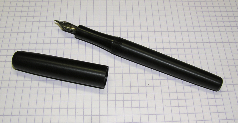
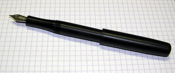
One of my favorite drafting pencils in regular rotation is the Pilot S20. I really enjoy the shape of the grip section. For this design, I tried to copy the general shape as much as possible. It turned out pretty close, if I do say so myself. I intend to use this as-is for the next couple of weeks and see how I like the shape. If everything is to my liking, I'll go ahead and make a more finished product out of the acrylic blanks that I have.
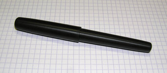
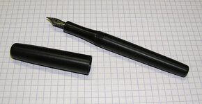
I'll be sure to post the finished product when the time comes, but for now, here is the prototype...
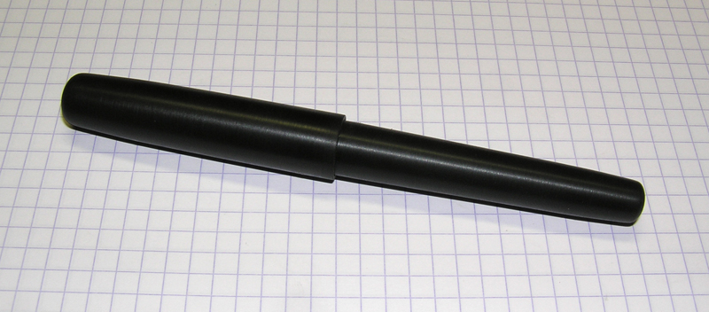
Some information about the pen:
Weight (uncapped) = 12 g
Weight (capped) = 18 g
Length capped = 5.1 "
Length uncapped = 4.875"
Length posted = 6.0"
I have now reserved a drawer in my toolbox for custom pen tooling. This is where it currently stands as of now.

The only other things I needed to make in addition were the woodturning rest and a couple of HSS lathe bits for threading and reaching into tight areas. And to think, I made all these parts just to make 3 parts! It of course took longer than I was hoping – but in the end it paid off. Once I had everything shown above, I probably only had a couple hours invested in the actual making of the pen.
This has definitely gotten a bit more lengthy than I originally intended. Hopefully some of you managed to make it the whole way through and found it interesting. I guess this is pretty much my take on making a custom pen with my background of dealing with metal parts. Maybe there will be some tips or tricks that some of you find useful.
If there's interest, I can reformat this into a tutorial – though I'm not sure what the process of submitting that would entail.
In any case, this was intended as something of a show and tell. Let me know if there is anything that's unclear or if you have questions about anything and I'll do my best to answer them.
I also decided that I wanted to make it myself – so I came here and started reading. This is the end result. I thought I would try to document everything I did and more importantly the thought process and reasoning behind why I did it – in case it could possibly benefit anyone else.
*******
I wanted to make as much of the pen myself. And since I really only planned on making myself a pen, I didn't want to spend an arm and a leg on custom tooling. Luckily for me, I have a fairly well outfitted machine shop in the basement so I set out to make everything I needed.
So I purchased some acrylic blanks from ExoticBlanks and added on some of the replacement Edison nibs with an order I placed at gouletpens. I initially thought about casting my own blanks from the outset but decided I didn't want to get too carried away.
And then the work began.
A little background about myself… I am a mechanical engineer with a little bit of machinist, welder, woodworker, and auto-mechanic thrown in there for good measure. I set out to draw what I wanted in CAD first. This is more or less what I came up with.
This was designed more or less without a clip in mind. That's only because I haven't figured out quite how I wanted to make one yet.
So my first design is a clipless version that is postable. I notice that many of the fountain pens that I've seen here and elsewhere have fairly short sections with the cap threads very close to where the pen is held. Though I haven't personally held many of these designs, I suspect that for most of these, I would find that uncomfortable. I tend to like a longer grip section. That is what drove most of the design of the pen.
For posting, there is a tapered section inside the cap that mates with a matching taper on at the rear of the pen.
I noticed while examining my Lamy Safari that inside the cap, there is a little rubber collet inside the cap that creates a seal just around the nib. I presume that feature is to prevent the nib from drying out between uses. I incorporated a similar feature in this pen, where the cap bottoms out against a chamfer on the front of the section. That should create a more or less air tight seal and to my mind, should provide the same functionality as some of the commercial features that I've seen. Time will tell I suppose.
[FONT="]So, up until this point, everything pretty much existed only on the computer screen. It was time to change that. First things first – there's obviously a bit of tooling that I'd need before I could make the actual pen. The #5 nib I was using was an M6.4x0.5mm thread. Not, shall we say, a common size (at least not in my world). I wasn't sure which size I wanted to start out with, so I also acquired a #6 nib. The #6 used an M7.4x0.5mm thread – though the major diameter measured closer to 7.2mm.
[/FONT]
The above image shows one of the #5 nib assemblies. One of the other things that I did, which I forgot to take pictures of, was that I trimmed away the material on the feed holder outside the dashed red lines to get rid of the raised lip at the front. To do that, I chucked the feed holder in the closest ER 32 collet in a hex collet block. Then I mounted the hex collet block on the 3-jaw in the lathe and turned it down with a very sharp tool. I did this because I wanted the feed holder to sit flush in a the counterbore at the front of the section.
As it so happens, a couple of years ago I acquired the metric change gears for my south bend 10k lathe, so I was in business. The first thing I set out to do was to make a hub with threads that fit the feed holders. The reason was to have a guage of sorts for the subsequent creation of a tap. The only problem was that I didn't have any internal threading tools that could fit through diameters that small. So, the actual first task was to make a tool to make a gauge to make a tap. Right..
After that, I used the internal threading tool to single point a female thread for each of the two feeds in a couple pieces of aluminum.
After this was complete, I started to make the two custom taps, using the aluminum hubs as a reference. The stock that I used was a spare grade 8 bolt that was left over from a previous project. The first step is basically to make a bolt with the appropriate thread form. I started by turning the major diameter, then cut the taper at the front, then cut the threads with a single point thread cutting tool.
Once I had a bolt that was just able to thread into aluminum hub, the next step was to cut the flutes. I did this using my milling machine with the help of an ER32 square collet block. There are a number of ways to make flutes. I happened to have a ball end mill of an appropriate size, so I used that. No matter how you go about doing it, the goal is to make sure that the cutting edge has some rake to it. When using a ball end mill, the easiest way to insure that you have a positive rake at the cutting edge is to cut with the end mill slightly off center. I've included a sketch to show how this is achieved.
Immediately after I had cut the flutes, the tap was in a virtually unusable state, 75% of the threads had a huge burr, thanks to the end mill. Note: most professionally made taps are ground, not machined and thus don't fall victim to this. So I used a small wire wheel on the dremel to remove the burrs. Tedious, but necessary. I also used the square collet block to machine the square flats in the driving end.
If I had been in need of cutting a thread into steel, I would have used a material that was hardenable. I had some 5/8" W1 tool steel (drill rod) around, but it wasn't worth the hassle to use for this much smaller diameter. As far as I know, the material used in grade 8 hardware is already quenched to achieve the 130 ksi yield strength they are spec'ed at. So heating this material up and quenching probably wouldn't achieve any increase in hardness. Since I only intend to use this on plastics, it wasn't really necessary to do anything further anyway.
I repeated the operation for a second tap that would fit the threads on the #6 feed holder.
[FONT="]I tested the taps on a couple of piece of scraps of delrin and was very pleased with the fit.
[/FONT]
Ok. The next gaps in tooling were for the section-to-body threads and the cap-to-body threads. After going through the design process for this first pen, using the #5 nib, I can definitely see how all the dimensions of the pen are driven by the dimensions of the feed. In my job, I tend to work with highly stressed metal components – so designing a pen with areas that have wall thickness on the order of ~0.030" thick makes me a bit squeamish.
As a bit of a sanity check, I measured the wall thickness of the Lamy Safari in a couple of places. Sure enough, the pen I have been carrying faithfully in my jeans pants pocket has what seems like a miniscule wall thickness between the section and the body – yet in the month or so that I've been carrying it I haven't broken it yet. I'll cross my fingers..
Now for the pen body-to-cap joint. Here, I wanted to use a triple start thread. This was mostly driven by the desire to minimize the number of turns to take the cap off during use. But there was also a small part of me that wanted to do it because I've never done it before – and I like challenging myself. I have kind of been intrigued with multi-start threads ever since I first learned about them in college while talking with one of the machinists I used to work with.
I decided on an M12x0.8mmx2.4L thread (major diameter = 12 mm, pitch = 0.8mm, lead = 2.4mm). So, custom triple start thread, here goes nothing..
I started with the male tap as that seemed the easiest place to begin. I again single pointed this thread, although there was a bit more complexity with this being a triple start thread. Here, I turned between centers. That is to say, that I drilled a 60 degree center in either end of the tap. In the three jaw chuck, I mounted a piece of steel and turned a 60 degree center in place. This insures that the center is aligned with the headstock axis. I then mounted the tap between the dead-center in the chuck and a live-center in the tail stock. A simple, custom dog was made to drive the tap using the chuck jaws.
A triple start thread is nothing more than three individual threads separated by 120 degrees. With the tap mounted between centers, to cut the three threads in sync all I needed to do was change which jaw the dog was driven by. The tailstock could be loosened and the tap repositioned with a high degree of accuracy. It should be noted that this procedure can only be used for external threads. A different method must be used for internal threads as you can't very well support the part using the tailstock if you have to cut on the ID.
So, by the end of this procedure, I had another bolt which had the appropriate threadform. Since I didn't have a reference part to check the fit of the thread, I kind of winged the thread depth – when the proportions of the thread looked appropriate, I stopped.
I cut the flutes in this part, except this time, I only cut three flutes instead of four. No real reason for it, just on a whim. I didn't take the flutes back the whole way, in part because I was only making three flutes. With only three flutes, you can't use a caliper or micrometer to measure across the threads to check the size of anything – so I left a full diameter section for the sake of measuring the thread form later on if I should desire.
This full diameter section of thread turned out to be useful later when adjusting the split-adjustable die. (There's a picture that shows the final geometry of the tap after the discussion of the mating die).
As I mentioned already, I couldn't support the die on centers so I needed an alternative way of indexing the die while cutting the female thread. There may be other options for indexing, but the only one that I was readily familiar with was using the compound in-line with the lathe axis to shift the cutting tool over by a distance equal to the pitch. This way, I could cut one of the threads, index the cutting tool using the compound, and then cut the remaining threads. This worked out quite well and I found it to be faster than using the centers.
The difficult part about making the die (and internal threads in general) is that there's no good way to measure where you're at. Technically, you could make a casting of the threads and then extract it and measure off the casting. But that sounds like a lot of work, especially since it would have to be done while the part was still on the lathe to be at all useful.
When I started to go about making the die, there was one aspect of the process that I had not thought of in advance. Though my procedure up until this point had been no different than simply making a custom nut/bolt – there was a subtlety to it that I had neglected. In order to figure out when to stop I had just assumed that I would stop when the tap fit through the die. But as the thread form was starting to look finished, the tap (still was a full screw at this point) still wouldn't fit. I was left scratching my head.
Fed up that things did not appear to be going smoothly, I decided to let it sit until the next morning. Thankfully, I walked away before I did something rash and wasted all my effort up to that point.
Upon thinking about the problem further, I realized the subtle thing that I had been missing. If the tap and die fit together perfectly, the threads that they cut would (in theory) also fit together perfectly. But if there is any looseness in the fit of the tap/die, the threads that they cut would have interference. So necessarily, when making the die – I couldn't use the tap to check the fit. By the time that it fit, the die would be too large (slightly).
That still left me with a dilemma. When to stop removing material? I decided to guess. I took another couple passes until the thread form looked just about right when using my loupe. I kept going until I said to myself, "Just one more pass."
Aside: I have a rule that I try to follow. I think I read about this somewhere specifically with regard to painting. But I find that it's applicable to many situations. Any time that I say to myself, "Just one more…", I stop there. I find that usually by the time I say "just one more" I'm already 95% of the way finished with whatever I was doing. Usually there's some risk involved in going too far and it may well be better off to stop at 95% than try to get that last little bit without going over.
So I stopped when the internal thread in the die looked about right. I took it off the lathe, went over to the mill and used a stub length drill bit to create the cutting edges. Cleaning out the burrs from this process was quite a bit more tedious than for the tap as I had to do each tooth manually.
Unfortunately, it was only after I was looking through pictures after the project was complete that I realized I neglected to take any pictures of the die threading operation while everything was still on the lathe. Oops..
Twenty minutes later, I had something that looked rather like a regular solid 1" die. I chucked up a piece of delrin, turned it so that it had a 12mm major diameter and used the die to cut a thread. And you know what? It was awful. Absolutely terrible. The thread was torn, rough, and all around pretty crappy.
So I tried it again, but this time I reduced the major diameter by a bit. And this one was better. Still terrible, but somewhat less terrible than the first one. So I realized that the die was just a bit too small as it was displacing way too much material. I thought maybe I would have gotten lucky and my "looks just about right" would have resulted in exactly the perfect fit I wanted. Not so.
[FONT="]So I set about turning the then solid die into a split-adjustable die. I drilled and tapped the die for an 8-32 set screw and then used a slitting saw to segment one side of the die. Here the threads are on the entry side. So as you thread the setscrew in, it bears against the other side of the die, causing it to spring open.
[/FONT]
I shortened an 8-32 set screw in the lathe and turned a reduced diameter section to pass through the threads. This worked like a charm.
It was at this point that I realized why all of the other split dies I had measured were on the order of 0.990". I had left the material at the original 1" diameter and when I applied the set screw to slightly expand the die, it no longer fit into my 1" die hold. D'oh. It's the little oversights sometimes that make me laugh. Easily fixed however.
To set the size of the die, I used the full thread portion I had left on my tap. I opened the die until it would just thread over the tap. Then I loosened the screw slightly to relax the die so that it would cut a thread with a hint of clearance. In the end I was able to make what I feel is a very pleasing fit between the mating threads.
Having two parts fit together perfectly knowing that I was responsible for every part of the process was quite satisfying. After completing this part of the project, I can definitely see why quality taps and more specifically dies are so pricey. It's a good thing that my time is "free."
A macro look at one of the split adjustable dies…
The next thing was to repeat the process for the section-to-body threads. Here, I decided to go with a 3/8"-36tpi – 12tpi lead triple start thread. That diameter worked better in my design than the more commonly used 10mm. Mostly was an arbitrary decision.
[FONT="]I won't repeat the description of the process as it was predominantly the same as the one I already described. The only thing I'll mention is my reasoning for going with an English thread as opposed to the more typical M10 at this size range. The reason was twofold. First, I wanted to put the gearing on the lathe back to its original state. The metric change gears that I purchased are not of the same quality as the stock gearing. One of the gears has a bit of a loose fit on the hub that it rides on and ultimately this introduces noise into the gear train which I find annoying. Second and probably more importantly, when using the metric change gears, in order to cut a thread you can't disengage the half-nuts. So you take one pass, then you have to reverse the lathe to move the cutting tool to its original position, lest you lose the timing with the lead screw. Cutting standard (English) threads is much easier because you can disengage the half-nuts and using the thread dial to get the timing correct. It makes for a much faster threading operation and less start/stops on the motor.
[/FONT]
Once I had cleaned all the burrs and crap out of the threads in the various taps I made, I used a cylindrical stone bit mounted in the dremel to sharpen up the flutes. The bits that I used are advertised as being "chain saw sharpening stones." Seemed to work quite well. I also used this to sharpen the inside "flutes" of the dies.
The last bit of tooling (or so I thought) that I required was something to aid in the machining of the inside of the cap. There were some fairly specific features that required close control on the tolerances in order for the cap to work the way I had intended. Here I made what is called a D-bit reamer. In this application, it amounts to a single flute form cutting tool.
The process is as follows: First, you cut the male version of what the finished bore should look like. It's much easier to control the dimensions of outside diameter (since they are so easily measured). Then you machine away almost half of it. The goal is to cut about 0.005" above center – this is important (from what I've read). Cutting more than half way would result in the tool cutting smaller than it should. Cutting it slightly above center gives you some extra material left for sharpening.
I left a full diameter section at both ends. The one at the right would later be machined away, but it provided a second hold down point once mounted at the milling machine.
Some relevant background info on d-bit reamers that I found while I was doing some research for this project…
Why are these called d-bit? If you look at the tool from the front, the cross section looks like a D with half of the diameter removed. Simple as that.
While I used this technique to create a form tool, that doesn't have to be the case. You could just as easily start with a right circular cylinder of the correct diameter, cut the D-shape, sharpen, and voila – you have a custom sized drill bit/reamer. Handy in a pinch if you don't have the time to wait for a specialty tool. Diagram shown below.
In operation, you would begin by creating a starter hole using a drill bit the next fractional size smaller than whatever your reamer is. Then, for the most accurate hole you would using a boring tool to create the exact size you want to a depth of 1-2 times the diameter. This will provide a good starting point (in terms of straightness) for the reamer and will enable it to follow that surface along the length of the whole. Because the d-bit reamer was cut on-size, it more or less acts like it's own pilot surface – but it needs help at the entry to the hole.
This technique is used quite often for machining custom chambers by the gunsmithing community. If you're interested google "d-bit chamber reamer" or just "chamber reamer."
Regarding the use of this technique in other applications and for different materials: If you were going to use a d-bit reamer to cut metal (steel, aluminum, etc), you would need to heat treat it in order to harden the cutting edge. Also, while cutting metals, go slow and use lots of cutting fluid.
The order of operations between cutting away half the body and hardening depends on the intended accuracy of what you're trying to do. If you wanted the utmost accuracy out of the end product, you would harden the reamer first and then remove half the body. The difficulty is that you would then need to grind away all that material, since you've just hardened the whole thing. The result however is that because you quenched the part while it was still solid – it had an even section thickness the whole way through and that should have minimized the possibility of the part warping.
If you machined away half the body (well, ~0.005" less than half), then heated and quenched the part – you could potentially introduce some warp. How much depends on a lot of factors. As I will not be cutting anything out of steel with this tool – I can thankfully skip the heat treating step altogether.
In all cases, once you have the D shape, you'll need to sharpen the tool. This is accomplished by running the flat against a sharpening stone. I have a number of large stones for sharpening my kitchen knives and I already had them out – so I went with that.
This form tool will perform the following functions. 1) Create clearance for the nib. 2) Form the chamfer where the cap will bottom against the section. 3) Form the taper where the cap would sit when posted. 4) Cut the minor diameter for the cap threads 5) Locate all of the features at the appropriate depth and in relation to one another.
Once I had decided to go this route, it became obvious to me that the level of effort required to remake additional copies of my pen was dropping quite drastically. Though I had initially only intended to make one for myself – now I can imagine all of my close friends and family will be receiving fountain pens as their gifts at major holidays for at least the next year.
Though I'm sure many of them would prefer a design that has a clip.. That will be next.
For turning the exterior geometry of all the components, I opted to make custom mandrels rather than struggle trying to hold them in some other fashion. Each of these mandrels was designed to grasp onto two different diameters to hold the parts securely. Each of the mandrels had a custom bolt with a tapered head. The tapered head engaging a matching taper in the mandrel is what caused the expansion. I cut the slits with a slitting saw, 3 slits for the larger one and 2 for the smaller one.
For the section, instead of an expanding mandrel, I just made a pair of bushings that threaded together. One end of the bushings were drilled for a center, so that I could later support them with the tail stock.
Last but not least – the final thing that I needed to do was to create a fixture that would allow me to use wood lathe tools on my metal lathe. So I built a small toolpost which fit onto the cross slide in place of the compound. As it turned out, I already owned the tool-rest, I just didn't know it. By that I mean, I was able to make it from materials that I already owned. That's always a nice feeling.
It attached in place of the compound and is adjustable in height/orientation by means of a thumb screw. I made the thumb screw from a spare bolt and wingnut welded together. I also added a brass tip to the thumbscrew to prevent it from damaging the shaft it locks in place. All in all it works fairly well, although I think that I ended up making it a little too tall even in the lowest position, so I'll have to modify that at some point.
Once all of these extraneous bits of tooling were completed, the act of actually making the first pen went by fairly quickly. I opted to make the first prototype out of delrin as I had a bunch of it and I didn't want to waste the couple acrylic blanks I had ordered on what could very well be a bunch of screw up attempts.
Before I started, I got out all the various drills and taps I would need and set up some cheap depth stops using masking tape. That worked out pretty well. Even though I made drawings of the parts, dimensioning everything quite closely, I only really used them as a reference and made everything to fit as I went along.
These were just the tools for the internal geometry of the cap and the body.
All in all, everything proceeded pretty smoothly. The D-bit reamer was a first for me and was very easy to use. To be able to quickly and easily machine a number of precise features in a small diameter bore where you would otherwise be working blind – well, let's just say it was well worth the time spent making it.
Making the cap…
I ended up shaping the exterior of the cap and body with the standard metal lathe tools and a bit of filing. The compound was essential in cutting a taper on the rear of the body which matched the angle of the taper cut into the cap.
For the section, I opted to use the wood lathe tools to turn the contour to my liking. I ultimately decided to remove the chuck and use the lathe's collets. I was initially getting set up to do it with the 3-jaw chuck, but had a flash of what could have happened if I slipped and the tool – or my hand – got caught up in the lathe jaws. Definitely worth the couple extra minutes to work safe.
I got pretty lucky with my lathe. The previous owner sold a set of collets (odd size -> 6K) along with the lathe. The largest diameter the set goes to is 5/8" but it's been plenty for most of my projects. Very handy.
One of my favorite drafting pencils in regular rotation is the Pilot S20. I really enjoy the shape of the grip section. For this design, I tried to copy the general shape as much as possible. It turned out pretty close, if I do say so myself. I intend to use this as-is for the next couple of weeks and see how I like the shape. If everything is to my liking, I'll go ahead and make a more finished product out of the acrylic blanks that I have.
I'll be sure to post the finished product when the time comes, but for now, here is the prototype...
Some information about the pen:
Weight (uncapped) = 12 g
Weight (capped) = 18 g
Length capped = 5.1 "
Length uncapped = 4.875"
Length posted = 6.0"
I have now reserved a drawer in my toolbox for custom pen tooling. This is where it currently stands as of now.
The only other things I needed to make in addition were the woodturning rest and a couple of HSS lathe bits for threading and reaching into tight areas. And to think, I made all these parts just to make 3 parts! It of course took longer than I was hoping – but in the end it paid off. Once I had everything shown above, I probably only had a couple hours invested in the actual making of the pen.
This has definitely gotten a bit more lengthy than I originally intended. Hopefully some of you managed to make it the whole way through and found it interesting. I guess this is pretty much my take on making a custom pen with my background of dealing with metal parts. Maybe there will be some tips or tricks that some of you find useful.
If there's interest, I can reformat this into a tutorial – though I'm not sure what the process of submitting that would entail.
In any case, this was intended as something of a show and tell. Let me know if there is anything that's unclear or if you have questions about anything and I'll do my best to answer them.
Attachments
-
 finished_capped.jpg225.3 KB · Views: 3,043
 -
 finished_posted.jpg160.5 KB · Views: 2,964
 -
 mougeottedesign1c.jpg37.7 KB · Views: 3,531
 -
 mougeottedesign1d.jpg58.7 KB · Views: 3,577
 -
 mougeottedesign1b.jpg43.5 KB · Views: 3,589
 -
 mougeottedesign1a.jpg37 KB · Views: 3,542
 -
 mougeottedesign1zoom.jpg106.2 KB · Views: 3,508
 -
 finished_uncapped.jpg183.7 KB · Views: 3,065
")


