monophoto
Member
Recently, I tried making a walking cane – mainly to prove that I could do it. Here are a few thoughts based on that initial experience:
1. Length: Ideally, canes are sized to match the user. The ideal length, including the handle, is the distance between the floor and the user's wrist joint while standing. Obviously, this doesn't need to be rocket science, but if there is to be an error, it is better to err on the side of slightly too long.
2. Diameter: my research didn't disclose any suggestions on diameter. Canes aren't intended to support the user's weight; instead, the purpose of a cane is to assist in maintaining balance when the user is weak on one side. But one has to be concerned about the consequences of unexpected failure of a cane that causes the user to fall. I found one YouTube video in which the maker chose to drill out the shaft and glue in a length of steel all-thread rod. That would definitely be strong, but it would also add a lot of weight. However, it seems to me that the goal is to be strong enough without being too heavy, with diameter and the characteristics of the timber selected for the project being the key design factors. I made mine from ash, and turned the shaft to a 1 1/8" diameter. In retrospect, I suspect it could have been a bit thinner – perhaps 1".
3. Constructability: This was the most difficult technical challenge. Turning the shaft as a single spindle sounds like a great idea, but that requires a lathe with a long bed as well as a steady-rest. I don't have a steady, and my midi-lathe bed is only 18". It didn't make sense to purchase a bed extensions for one project and I don't really have enough room in my shop for a longer bed. So I opted to turn the shaft in three sections that were glued together using mortise and tenon joints. There are several elements that contribute to the strength of this construction:
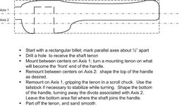
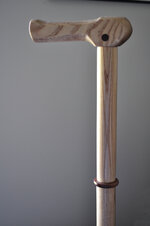
4. Handle: there are two options to choose from – a knob (essentially, a turning that looks much like a bottle stopper, only larger), or a handle. I chose to use a handle turned in three steps on two axes. I started with a blank with a rectangular cross section and with a hole drilled in one side to receive the shaft tenon. The first turning between centers was to put a spigott on one end for remounting later. Next, I remounted the blank on the parallel axis (again between centers) to shape the top of the handle. Third, I remounted it again, gripping the spigot in a chuck and with the tailstock for support to shape the bottom of the handle (leaving the area where the shaft would attach flat). In this stage, I was able to turn away the evidence of the second turning and its axis, before reshaping the spigott into a 'nose' and parting off. Final sanding smoothed everything and removed the tailstock dimple from the second axis turning.
5. Attaching the handle: I opted to use a dowel pin that that runs from side to side through the handle and the shaft tenon. I used contrasting wood so that the dowel became a decorative element. Another option is to use a dowel (perhaps fiberglass) that runs longitudinally in a blind hole inside the handle on Axis 1 (ie, it enters from the back of the handle, but stops before it reaches the front). There is an opportunity to drill the mortise hole for that rod as part of the second turning. The hole can later be disguised with a single plug that is sanded smooth. This approach is a bit more work, but it may create a stronger handle, and it has the advantage of also eliminating a tailstock dimple left from turning on Axis. Both of these options probably fall into the 'belt and suspenders' category, and simply gluing a shaft tenon into a mortise in the handle might be adequate.
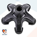
6. Foot: you can purchase metal ends for canes, but the simpler choice is a rubber foot from the hardware store. They are available in either white or black, and in a selection of diameters. It's prudent to check the sizing before finish turning the shaft. Ideally, the foot will fit snugly, but it is always possible to add some polyurethane glue to hold it in place.
7. Finish: canes get rough use, so the finish needs to be fairly tough and/or amenable to repairs. I was torn between wipe-on Polyurethane and a commercial Modified Tung-oil finish; I chose the Tung-oil finish because it would be less 'plasticky' and has a reputation for being easily refinished if necessary.
Rather than turning a handle, it is possible to purchase handles. Timberlines.com is a specialty supplier of cane components and offer handles, shaft couplers (to make collapsible canes for travel), and metal feet. Lee Valley also carry some cane components.
Bottom line: it was a fun project that didn't require any tooling that the ordinary woodturning shop isn't likely to have, and it has a practical use. My total out-of-pocket cost for the project was less than $5 for the rubber foot (actually for a package of four – I now have three spares for future projects). I don't need a cane today, but you never know what the future might bring!
1. Length: Ideally, canes are sized to match the user. The ideal length, including the handle, is the distance between the floor and the user's wrist joint while standing. Obviously, this doesn't need to be rocket science, but if there is to be an error, it is better to err on the side of slightly too long.
2. Diameter: my research didn't disclose any suggestions on diameter. Canes aren't intended to support the user's weight; instead, the purpose of a cane is to assist in maintaining balance when the user is weak on one side. But one has to be concerned about the consequences of unexpected failure of a cane that causes the user to fall. I found one YouTube video in which the maker chose to drill out the shaft and glue in a length of steel all-thread rod. That would definitely be strong, but it would also add a lot of weight. However, it seems to me that the goal is to be strong enough without being too heavy, with diameter and the characteristics of the timber selected for the project being the key design factors. I made mine from ash, and turned the shaft to a 1 1/8" diameter. In retrospect, I suspect it could have been a bit thinner – perhaps 1".
3. Constructability: This was the most difficult technical challenge. Turning the shaft as a single spindle sounds like a great idea, but that requires a lathe with a long bed as well as a steady-rest. I don't have a steady, and my midi-lathe bed is only 18". It didn't make sense to purchase a bed extensions for one project and I don't really have enough room in my shop for a longer bed. So I opted to turn the shaft in three sections that were glued together using mortise and tenon joints. There are several elements that contribute to the strength of this construction:
- Making the joints long enough to get a good long-grain to long-grain bond. I would be hesitant to use tenons shorter than 1"
- Making sure that each tenon bottoms out in its mortise. A gap at the bottom of a mortise will be a weak point in the shaft
- Making the walls of the mortises about as thick as the diameter of the tenon. Practically, the mortises have to be drilled using whatever bits are available, and the tenons then fine-tuned to fit.
- Using a good quality PVA glue to assemble the joints.
4. Handle: there are two options to choose from – a knob (essentially, a turning that looks much like a bottle stopper, only larger), or a handle. I chose to use a handle turned in three steps on two axes. I started with a blank with a rectangular cross section and with a hole drilled in one side to receive the shaft tenon. The first turning between centers was to put a spigott on one end for remounting later. Next, I remounted the blank on the parallel axis (again between centers) to shape the top of the handle. Third, I remounted it again, gripping the spigot in a chuck and with the tailstock for support to shape the bottom of the handle (leaving the area where the shaft would attach flat). In this stage, I was able to turn away the evidence of the second turning and its axis, before reshaping the spigott into a 'nose' and parting off. Final sanding smoothed everything and removed the tailstock dimple from the second axis turning.
5. Attaching the handle: I opted to use a dowel pin that that runs from side to side through the handle and the shaft tenon. I used contrasting wood so that the dowel became a decorative element. Another option is to use a dowel (perhaps fiberglass) that runs longitudinally in a blind hole inside the handle on Axis 1 (ie, it enters from the back of the handle, but stops before it reaches the front). There is an opportunity to drill the mortise hole for that rod as part of the second turning. The hole can later be disguised with a single plug that is sanded smooth. This approach is a bit more work, but it may create a stronger handle, and it has the advantage of also eliminating a tailstock dimple left from turning on Axis. Both of these options probably fall into the 'belt and suspenders' category, and simply gluing a shaft tenon into a mortise in the handle might be adequate.
6. Foot: you can purchase metal ends for canes, but the simpler choice is a rubber foot from the hardware store. They are available in either white or black, and in a selection of diameters. It's prudent to check the sizing before finish turning the shaft. Ideally, the foot will fit snugly, but it is always possible to add some polyurethane glue to hold it in place.
7. Finish: canes get rough use, so the finish needs to be fairly tough and/or amenable to repairs. I was torn between wipe-on Polyurethane and a commercial Modified Tung-oil finish; I chose the Tung-oil finish because it would be less 'plasticky' and has a reputation for being easily refinished if necessary.
Rather than turning a handle, it is possible to purchase handles. Timberlines.com is a specialty supplier of cane components and offer handles, shaft couplers (to make collapsible canes for travel), and metal feet. Lee Valley also carry some cane components.
Bottom line: it was a fun project that didn't require any tooling that the ordinary woodturning shop isn't likely to have, and it has a practical use. My total out-of-pocket cost for the project was less than $5 for the rubber foot (actually for a package of four – I now have three spares for future projects). I don't need a cane today, but you never know what the future might bring!