
I purchased a PowerMatic 3520C about a month or so ago (maybe closer to two now). Just turned it on today...and it seems to trip the breaker when I turn up the RPM above 0. It powers on fine, the RPM meter lights up, the green on light lights up when I press the green button, and it'll be fine until I turn up the RPM...
It was on sale when I bought it, $4800 plus extras valued at a couple hundred more. List price on these things now is around $5700, and I just couldn't pass up the opportunity. Well, it shipped and arrived a heck of a lot faster than I expected, and was delivered before I had a chance to install 240V power for it. I had a few electricians come by, and the price just to install a GFCI two-pole 20A breaker, some romex and an outlet was anywhere from $1600 to a whopping $2156. After pricing out the parts myself (a few hundred bucks...romex is expensive nowadays, $108 just for some 12/2, $218 for 12/3, the GFCI breaker was $104, plus a few other parts), realized these guys were trying to take me for a ride with the labor charges.
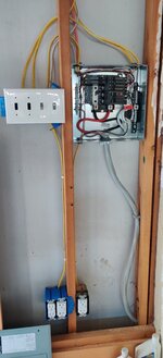
I ended up wiring in the new breaker, romex and a twist-lock 240V outlet myself (along with a few other things, like a light switch for my new overhead shop lights, a switch and some new GFCI outlets for my drill press and bandsaw, etc.) I triple tested everything with my multimeter, and its all good. I get 123.8v from ground to either black and white (normally red, but I used 12/2 to save some money), and 248V between black and white. This is true at every point along the path from the breaker to the outlet, at the three wires at the other end of the power cable that came with the lathe (which I wired into a 240V twist-lock plug), as well as from the 1 (black) and 3 (white) terminals inside the main switch box in the PowerMatic itself. The power is rock solid stable, it fluctuates maybe ~0.1V occasionally, but otherwise its super stable. So, I believe everything is wired up properly...I don't think there are any ground faults within the wiring job itself from the breaker to the end of the power cable anyway.
With all of that new wiring installed and tested, today I finally had some people come by to help me set up the lathe. It was heavier than I expected...online I thought I saw that the weight was 430lb, turned out to be 726lb in total...so it took three of us to set everything up, and maneuver the bed and stand around, and finally get the headstock on. Finally connected the power cable to the on/off master switch on the back of the lathe, and powered it up for the first time (yes, sadly, probably close to two months after I bought it!! ) After a moment the lights came on, and I thought I was in business...until I turned up the RPM. I am curious why the lathe would power on fine, and show the control panel lights and all that...and only trip the moment I try to turn up the RPM? I am going to be calling PowerMatic on monday of course, but I'm curious if anyone can think of a reason why this might be happening? Its tripping the GFCI breaker...I suspect its a ground fault, as the red indicator on the breaker appears...but, the fault only seems to occur when the motor finally starts to rotate. This lathe seems to have a VFD to control the motor, probably because it is a 3-phase motor. The VFD has a little plastic cover on the back, and if I pull that out I can see a port of some kind...which makes me wonder if it can be tweaked or tuned to account for differences in voltage?
The manual says the motor requires 230V 1-phase power, and my power is single-phase, but its nearly 250V... Is it possible that the extra 20V of voltage is causing a problem? Or is there more likely a problem with the motor itself? OR something with the VFD?
Thanks...
It was on sale when I bought it, $4800 plus extras valued at a couple hundred more. List price on these things now is around $5700, and I just couldn't pass up the opportunity. Well, it shipped and arrived a heck of a lot faster than I expected, and was delivered before I had a chance to install 240V power for it. I had a few electricians come by, and the price just to install a GFCI two-pole 20A breaker, some romex and an outlet was anywhere from $1600 to a whopping $2156. After pricing out the parts myself (a few hundred bucks...romex is expensive nowadays, $108 just for some 12/2, $218 for 12/3, the GFCI breaker was $104, plus a few other parts), realized these guys were trying to take me for a ride with the labor charges.
I ended up wiring in the new breaker, romex and a twist-lock 240V outlet myself (along with a few other things, like a light switch for my new overhead shop lights, a switch and some new GFCI outlets for my drill press and bandsaw, etc.) I triple tested everything with my multimeter, and its all good. I get 123.8v from ground to either black and white (normally red, but I used 12/2 to save some money), and 248V between black and white. This is true at every point along the path from the breaker to the outlet, at the three wires at the other end of the power cable that came with the lathe (which I wired into a 240V twist-lock plug), as well as from the 1 (black) and 3 (white) terminals inside the main switch box in the PowerMatic itself. The power is rock solid stable, it fluctuates maybe ~0.1V occasionally, but otherwise its super stable. So, I believe everything is wired up properly...I don't think there are any ground faults within the wiring job itself from the breaker to the end of the power cable anyway.
With all of that new wiring installed and tested, today I finally had some people come by to help me set up the lathe. It was heavier than I expected...online I thought I saw that the weight was 430lb, turned out to be 726lb in total...so it took three of us to set everything up, and maneuver the bed and stand around, and finally get the headstock on. Finally connected the power cable to the on/off master switch on the back of the lathe, and powered it up for the first time (yes, sadly, probably close to two months after I bought it!!
) After a moment the lights came on, and I thought I was in business...until I turned up the RPM. I am curious why the lathe would power on fine, and show the control panel lights and all that...and only trip the moment I try to turn up the RPM? I am going to be calling PowerMatic on monday of course, but I'm curious if anyone can think of a reason why this might be happening? Its tripping the GFCI breaker...I suspect its a ground fault, as the red indicator on the breaker appears...but, the fault only seems to occur when the motor finally starts to rotate. This lathe seems to have a VFD to control the motor, probably because it is a 3-phase motor. The VFD has a little plastic cover on the back, and if I pull that out I can see a port of some kind...which makes me wonder if it can be tweaked or tuned to account for differences in voltage? The manual says the motor requires 230V 1-phase power, and my power is single-phase, but its nearly 250V... Is it possible that the extra 20V of voltage is causing a problem? Or is there more likely a problem with the motor itself? OR something with the VFD?
Thanks...
 I could understand a few hundred bucks to do that, a pro shouldn't need much more than an hour to do something that simple....but these guys are of their rocker for what they are asking for a basic install. The labor cost these guys are asking for around here is incomprehensibly insane.