BigShed
Member
Having been inspired by 2 pen turners, Penpal and Skiprat, I have made a pen mill attachment for my milling machine. Penpal made his from a Clisby Miniature metal lathe, Skiprat made his from scratch as an attachment to his metal lathe.
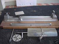
I was going to use Skiprat's idea and adapt it to be used on my mill but a couple of weeks ago I picked up an old wood turning attachment for a power drill from Ebay (photo 1). It cost me the princely sum of $20, couldn't have bought the aluminium need for that!

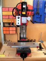
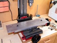
As the overall length, even after I cut the attachment bed in half, exceeded the length of the mill table I had to provide a base plate which attached to the miil and in turn takes the pen mill attachment (photos 2 & 3)
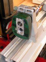
As the turning attachment was designed to take a 42mm collar of a power drill I decided to use the front part of an old, dead, Bosch drill that has been kicking round the shed for years (one day...........). I cut the front of the drill off just behind the gear box and milled the whole thing flat.
(photo 4)
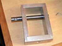
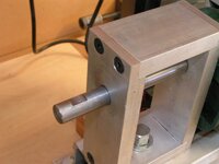
I then made up a frame from 40x12 aluminium to take a 12mm shaft which has been drilled with an 8mm recess to slip over the Bosch drill shaft and attached with a 3mm grub screw. (photos 5 and 6)
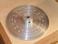
Next was making a 6mm thick aluminium plate, turned to 160mm diam on the metal lathe, fitted with an aluminium bush and attched to the 12mm shaft with a grub screw (flat milled on shaft).(photo 7)
At present there are 2 sets of index holes in this dividing plate, 1 set of 12 and 1 set of 18, have another groove left for another set.
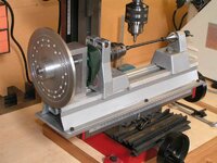
The whole thing fits together quite nicely (photo 8), next step is to mill some logitudinal grooves in pen blanks, or flats, and start playing.
Another addition to this contraption will involve extending the X axis lead screw and put a small gear on this to drive the divider plate to achieve some spirals, as Skiprat has done and similar to the Beall contraption.
Am I having fun yet? You bet!

I was going to use Skiprat's idea and adapt it to be used on my mill but a couple of weeks ago I picked up an old wood turning attachment for a power drill from Ebay (photo 1). It cost me the princely sum of $20, couldn't have bought the aluminium need for that!

As the overall length, even after I cut the attachment bed in half, exceeded the length of the mill table I had to provide a base plate which attached to the miil and in turn takes the pen mill attachment (photos 2 & 3)
As the turning attachment was designed to take a 42mm collar of a power drill I decided to use the front part of an old, dead, Bosch drill that has been kicking round the shed for years (one day...........). I cut the front of the drill off just behind the gear box and milled the whole thing flat.
(photo 4)
I then made up a frame from 40x12 aluminium to take a 12mm shaft which has been drilled with an 8mm recess to slip over the Bosch drill shaft and attached with a 3mm grub screw. (photos 5 and 6)
Next was making a 6mm thick aluminium plate, turned to 160mm diam on the metal lathe, fitted with an aluminium bush and attched to the 12mm shaft with a grub screw (flat milled on shaft).(photo 7)
At present there are 2 sets of index holes in this dividing plate, 1 set of 12 and 1 set of 18, have another groove left for another set.
The whole thing fits together quite nicely (photo 8), next step is to mill some logitudinal grooves in pen blanks, or flats, and start playing.
Another addition to this contraption will involve extending the X axis lead screw and put a small gear on this to drive the divider plate to achieve some spirals, as Skiprat has done and similar to the Beall contraption.
Am I having fun yet? You bet!

Attachments
-
 ebay_wood lathe attachment_3968_1.JPG11.3 KB · Views: 240
 -
 20090318_003_small.jpg43.3 KB · Views: 223
 -
 20090318_002_small.jpg83.6 KB · Views: 177
 -
 20090318_011_small.jpg37.1 KB · Views: 219
 -
 20090318_012_small.jpg60.4 KB · Views: 173
 -
 20090318_007_small.jpg50.3 KB · Views: 160
 -
 20090318_009_small.jpg57.5 KB · Views: 170
 -
 20090318_015_small.jpg81.8 KB · Views: 276
Last edited:

