Delta/Rockwell Homecraft drill press

Signed-In Members Don't See This Ad

InkyMike

Member
Joined
Jun 28, 2016
Messages
403
Location
Maple Valley, WA
Hello everyime

Is anyone here using an older Delta/Rockwell Homelight drill press (or does anyone have experience with them?) I picked up a 1957 11" bench top version the other night. It has some issues with runout , but my dad is a machinist and we will be able to solve for that.

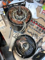
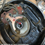
My question is regarding the motor. It ran like a top when I picked it up. Today, as I was measuring some runout, it would buzz longer before starting - the last time it buzzed and didn't start at all. I am guessing (and hoping) it's the starting capacitor.

Has anyone dealt with this? Any info and a source for a replacement cap? I figured I'd ask the collective here before I begin my Google quest.

Thanks much in advance
Michael
 
Signed-In Members Don't See This Ad

howsitwork

Member
Joined
Jul 9, 2016
Messages
2,320
Location
Thirsk
Does it have a centrifugal switch? Single phase motors often spin initially at slower speed on starter windings then the centrifugal switch clicks across and it runs at full speed on secondary windings. You might be able to test by flicking it round when turned on .

Did it give a flight click as it turned off when you first ran it and it worked ?
 

InkyMike

Member
Joined
Jun 28, 2016
Messages
403
Location
Maple Valley, WA
Does it have a centrifugal switch? Single phase motors often spin initially at slower speed on starter windings then the centrifugal switch clicks across and it runs at full speed on secondary windings. You might be able to test by flicking it round when turned on .

Did it give a flight click as it turned off when you first ran it and it worked ?
I'm not entirely sure

I was able to get it started once when it was buzzing by pulling on the belt. The last time it would not start by pulling the pulley and it smoked just a wee bit. I'm afraid I'll damage it more by trying it again

I want to say it gave a slight click when I turned it off but I don't recall.

Edit: I tried it again and spun the belt to get it moving. There is a faint click at the end when it's shutting off.
 

InkyMike

Member
Joined
Jun 28, 2016
Messages
403
Location
Maple Valley, WA
@howsitwork was correct - it has a centrifugal switch. I pulled off the back - everything was pretty dirty, so I sprayed it out with contact cleaner and used a Dremel plastic brush tool to clean off the armature. I got it all back together and it fired up about 4 out of 5 times. One time I still needed to spin the belt to get it going. I'm not sure what else to do to the centrifugal switch. Nothing looked like it was misaligned or sticking and it popped up and down manually pretty easily.

Michael
 

jttheclockman

Member
Joined
Feb 22, 2005
Messages
19,148
Location
NJ, USA.
@howsitwork was correct - it has a centrifugal switch. I pulled off the back - everything was pretty dirty, so I sprayed it out with contact cleaner and used a Dremel plastic brush tool to clean off the armature. I got it all back together and it fired up about 4 out of 5 times. One time I still needed to spin the belt to get it going. I'm not sure what else to do to the centrifugal switch. Nothing looked like it was misaligned or sticking and it popped up and down manually pretty easily.

Michael
It is probably a capacitor start motor and this can be a twofold problem. I say this because you said you saw smoke. That would mean the centrifugal switch is not opening after up to speed and that will burn starting winds. For it not to start can be a capacitor problem if you are turning to start. If intermittent it would be wise to replace both. If you hear the switch drop out when it gets up to speed then it is working but how well? The click you hear when turn off drill is the switch reengaging to start the cycle over again when called upon.
 

InkyMike

Member
Joined
Jun 28, 2016
Messages
403
Location
Maple Valley, WA
It is probably a capacitor start motor and this can be a twofold problem. I say this because you said you saw smoke. That would mean the centrifugal switch is not opening after up to speed and that will burn starting winds. For it not to start can be a capacitor problem if you are turning to start. If intermittent it would be wise to replace both. If you hear the switch drop out when it gets up to speed then it is working but how well? The click you hear when turn off drill is the switch reengaging to start the cycle over again when called upon.
The smoke I saw was from the front of the motor and the starter windings are in the back if I understand the design correctly. There is no capacitor that I can find having pulled the back off, and there is no external canister or holder for one. If there's a capacitor in there, I'm going to have to play where's Waldo to find it.

Below is the motor with the back off before I cleaned it out.
 

Attachments

  • 39219C52-D78E-4C77-A313-751847955B4D.jpeg
    39219C52-D78E-4C77-A313-751847955B4D.jpeg
    536.6 KB · Views: 64
Last edited:

jttheclockman

Member
Joined
Feb 22, 2005
Messages
19,148
Location
NJ, USA.
That is a split phase motor so no capacitor. If the motor does not start then either there is an open in the wiring somewhere or that centrifugal (starting) switch is not closing all the way and thus not making a circuit to starting section of wiring on coils. Use contact cleaner to clean contacts unless they are so pitted then sanding maybe needed. ( Here is one of those things that gets left out when explaining things, Do Not sand those contacts with sandpaper. Try some cardboard or a paper bag, or if have to just a couple swipes of 12,000 grit mm. You do not want to sand the plating off those contacts or they will ark and then just weld together after a few starts.) The spring on that thing needs to be in good shape too in order to disengage the starting windings when it reaches about 75% speed. This all happens in reverse when motor is shut down and those contacts need to make good contact again for next start up. If that switch does not open to allow running windings to take over you will burn out the starting windings. Motor will get real hot. One other thing since you are blowing dust out of that motor, be careful of any bearings and not get dust in them. Good luck. About all I can tell you.
 
Last edited:

InkyMike

Member
Joined
Jun 28, 2016
Messages
403
Location
Maple Valley, WA
That is a split phase motor so no capacitor. If the motor does not start then either there is an open in the wiring somewhere or that centrifugal (starting) switch is not closing all the way and thus not making a circuit to starting section of wiring on coils. Use contact cleaner to clean contacts unless they are so pitted then sanding maybe needed. ( Here is one of those things that gets left out when explaining things, Do Not sand those contacts with sandpaper. Try some cardboard or a paper bag, or if have to just a couple swipes of 12,000 grit mm. You do not want to sand the plating off those contacts or they will ark and then just weld together after a few starts.) The spring on that thing needs to be in good shape too in order to disengage the starting windings when it reaches about 75% speed. This all happens in reverse when motor is shut down and those contacts need to make good contact again for next start up. If that switch does not open to allow running windings to take over you will burn out the starting windings. Motor will get real hot. One other thing since you are blowing dust out of that motor, be careful of any bearings and not get dust in them. Good luck. About all I can tell you.
Thanks John. I've not worked on one of these before. I didn't sand any plating off, I just used a plastic brush in my Dremel to get some of the crud off. The switch seemed to move as it should and the springs didn't seem worn - again, not having seen a faulty one for comparison.

One thing I found was that wheel that spins that makes contact that looks like it has vertical teeth - some had some sharp corners and edges. I gently filed a few of them down. The contacts seem springy enough that they are making good contact.

I did give everything a good cleaning but I didn't focus on the switch and spring as much. May have to pull it apart again. My dad is reaching out to his network of folks to see if he can find a 1/2 model

Thanks for your advice. Much appreciated

Michael
 

jttheclockman

Member
Joined
Feb 22, 2005
Messages
19,148
Location
NJ, USA.
I'll have to do a little research on it. After having it apart, I would guess it's not overly complicated.
You got past the hard part of taking it apart. Everything is right there for you to see and easy to change. It maybe be hard finding those same switches and contacts. I would clean it up and just make sure those contacts are making good connections. You can check that with an ohm meter. Lot of dust in there. Also check condition of wires to make sure nothing was pinched. you can see if the switch goes up and down very easily Good luck.
 

jttheclockman

Member
Joined
Feb 22, 2005
Messages
19,148
Location
NJ, USA.
Thanks John. I've not worked on one of these before. I didn't sand any plating off, I just used a plastic brush in my Dremel to get some of the crud off. The switch seemed to move as it should and the springs didn't seem worn - again, not having seen a faulty one for comparison.

One thing I found was that wheel that spins that makes contact that looks like it has vertical teeth - some had some sharp corners and edges. I gently filed a few of them down. The contacts seem springy enough that they are making good contact.

I did give everything a good cleaning but I didn't focus on the switch and spring as much. May have to pull it apart again. My dad is reaching out to his network of folks to see if he can find a 1/2 model

Thanks for your advice. Much appreciated

Michael
If you are talking about the fins on the stator, that has nothing to do with the switch. Again you are concerned with the centrifugal part of the switch with the springs on it and also the contacts in the bell housing. That is the 2 parts to that switch. Contacts could look good and perform well but there could be a coating of dirt, oil or grease on them that prevent them from making good connections and maybe misaligned over time. That is where I would concentrate your problem.
 
Last edited:

InkyMike

Member
Joined
Jun 28, 2016
Messages
403
Location
Maple Valley, WA
Thank you. I found a couple videos on cleaning them, so I'll try that one more time. I gave the wires a once over and it didn't look like they were pinched. I didn't take the cover off the switch but I may need to give that a peek as well.
 

InkyMike

Member
Joined
Jun 28, 2016
Messages
403
Location
Maple Valley, WA
If you are talking about the fins on the stator, that has nothing to do with the switch. Again you are concerned with the centrifugal part of the switch with the springs on it and also the contacts in the bell housing. That is the 2 parts to that switch.
Yeah - that's what I was referring to. I now realize they don't matter. I'm guessing the sharp edges were a function of the manufacturing.

I'm going to pull it apart again this afternoon.
 

InkyMike

Member
Joined
Jun 28, 2016
Messages
403
Location
Maple Valley, WA
Update: Pulled the motor apart again tonight. Pulled out the pulley and the rotor. Gave it a cleaning. I made sure the switch was in good working order - the bit on the spindle looked like it was moving like it should and the spring looked okay.

I did some checking on the contacts. When open, there was a bit of resistance. When closed, there was almost none but not complete zero. I used 1500 grit and some contact cleaner. Still didn't get it completely to zero, but it seemed better.

Once it was all back together, it didn't fire up about 2 out of 5 times. But I cycled it about 20 more times and it fired right up every time.

I need to find a schematic for my specific motor. Curious why the switch has some resistance - not sure if there is some kind of resistive circuit under that little plate in the back of the bell housing.

In the meantime, hopefully it will keep chugging along. New chuck arrives tomorrow. Will be curious to see the runout. Longer term will be new bushings and hopefully an upgrade to a 1/2 HP motor.
 

jttheclockman

Member
Joined
Feb 22, 2005
Messages
19,148
Location
NJ, USA.
The rotor is what spins inside the stator housing. It has the centrifugal switch part mounted to it. This switch part needs to fly up and down with speed of motor. When it gets up to speed it opens a set of contacts that disconnect the starting windings and leaves the run windings connected. The starting windings are the smaller thinner wires on the coil, and it has the higher resistance values. The running windings are the thicker wires on the coil and has the lesser resistance values. When the contacts are closed both coils are connected if you put an ohm meter across the contacts you will read full resistance. I do not know how you are connecting the meter and to what. But to check contacts with wires you really need to use the terminals where the wires connect. But if you really want to test the contacts the best way is to disconnect all wires and just test contacts alone. Getting 2 different readings can mean you are reading either both run and start windings (highest ohm value) and the other way you can be reading just the run windings (lower value). Again not knowing where you are connecting the meter and what scale you are using.

To me if you are not going to change out that contact switch I would just make sure the contacts touch squarely and there is enough spring tension to make them touch well. Sometimes you need to bend the springy part of the contacts to put more tension on the contacts. This will make sure they touch every time. This could be why you are intermittingly getting a good start and sometimes not. And like I said clean the contacts well. A motor that old will loose it tension on the contacts as well as accumulate dirt on contacts along with just carbon because remember they are like a single pole switch opening and closing many times and slight arcs will cause carbon build up. This same thing happens often in the starting switch on a lathe and people complain their lathe does not start. Those switches can handle small amounts of current and the more carbon built up increase the resistance which means more current draw and thus more arcing. The contacts are where your problem seems to be and if you did what I suggest you should be fine. Good luck.

I just read again about your new chuck. Before you install make sure the mating parts are absolutely clean and free of any dust or dirt. Again a tool that old needs tender love and care and maintenance. Good luck.
 
Last edited:

InkyMike

Member
Joined
Jun 28, 2016
Messages
403
Location
Maple Valley, WA
Thanks John - below is a photo of the switch. I was measuring on Point A (the copper portion) and then B, which is under the coper assembly. If you were to look at it from the edge, you can see where the brass piece makes contact with the piece underneath when the brass piece is pushed up by the centrifugal switch. I will probably pull it apart again and check the terminals as you described.

The contacts do look like they are contacting squarely - I didn't put a feeler gauge in there to check the gap but looking at how high up the centrifugal switch. What's interesting about this is it seems opposite to what you describe above - there is no contact between the parts until the motor is running and the switch slides up - UNLESS that is what enables the run windings - if that is the case, I don't see where/how the starter windings are disconnected (or, to the second part of what you said, both windings stay connected...?)

I haven't pulled plate C off yet to see how it's all wired together.

The good news is I'm getting pretty fast at taking apart and putting it back together.
 

Attachments

  • motor 1.jpg
    motor 1.jpg
    220.9 KB · Views: 46

jttheclockman

Member
Joined
Feb 22, 2005
Messages
19,148
Location
NJ, USA.
Mike just because it looks like the contacts are touching does not mean there is enough tension on the connection and why I suggest maybe bending that springy part just a tad to add tension. Also the contacts can look like they are touching but if there is grime on them it will prohibit a good connection. But if you cleaned them then you should be fine. The wires you see come from the 2 coils in the stator and one set of 2 is for run circuit and other for start circuit. Yes that centrifugal switch expands after it start running and that fiber brown section loses contact with those 2 round fiber circle things that are connected to the contact plate. When the switch is engaged or in off state, they push that contact plate down and open the set of contacts. You see that when you operate the contacts I am sure. Those set of contacts are in series with the start windings. If you take those 2 or 4 screws holding that contact plate in, out you will see under that fiber board how the wires are run. I could draw you the circuit but do not know how to do that on the computer and add it to the thread. Sorry. But it is so simple circuit once you trace the wiring. remember you have the power chord connected under there also. just trace the wires to follow circuit. Under there is the terminals I am talking about. In the off state both windings are in the circuit via those set of contacts. That contact is broken and the start windings drop out. Now the circuit is complete through the run windings. I am trying to not to get too technical with you explaining parallel circuits and series circuits.
 
Last edited:

InkyMike

Member
Joined
Jun 28, 2016
Messages
403
Location
Maple Valley, WA
Thanks John - I'm still confused about one thing: the way this looks, when the switch is engaged it actually pushes the contact plate up to make a connection - it doesn't break the connection. There is no connection by default - at least not that I can see. Let me try draw a diagram later so I can try and show how I think it's working
 

jttheclockman

Member
Joined
Feb 22, 2005
Messages
19,148
Location
NJ, USA.
Thanks John - I'm still confused about one thing: the way this looks, when the switch is engaged it actually pushes the contact plate up to make a connection - it doesn't break the connection. There is no connection by default - at least not that I can see. Let me try draw a diagram later so I can try and show how I think it's working
I think we are getting into symantics. What is normal and what is taken apart stage. Here is what happens when you put that bell housing on, those contacts close because those fiber pieces are now touching. So yes in the state it sits now those contacts should be open. When all put together they close. Now when speed is reached that flywheel or fiber piece drops down and those contacts open. I hope this clears things up. Maybe we both are getting confused going back and forth.

Man I do not want to get into the technical end of this in any way to explain how the start windings are 90 degrees out of phase with run windings and all that stuff. But if you again look at the back of that fiber board and see the connections you will see that the run and start windings are connected in parallel with each other at start up and when speed is reached then the starting windings are dropped out and it runs on the run windings only.
 
Last edited:

jttheclockman

Member
Joined
Feb 22, 2005
Messages
19,148
Location
NJ, USA.
Thanks John - I'm still confused about one thing: the way this looks, when the switch is engaged it actually pushes the contact plate up to make a connection - it doesn't break the connection. There is no connection by default - at least not that I can see. Let me try draw a diagram later so I can try and show how I think it's working
Yes Mike you are correct. I explained in the above posting that I think we are getting confused to as what is natural state and taken apart state of this motor.
 

InkyMike

Member
Joined
Jun 28, 2016
Messages
403
Location
Maple Valley, WA
I guess what I'm missing is, when the part of the centrifugal switch pops up, I'm not seeing where it disconnects anything. Looking at the design it would seem the switch pushes on the Cooper arms, which would make a connection, not break it as it touches what looks like a contact behind it.

I'm going to need to pull it apart again at some point - maybe once I find the 1/2 HP donor motor.

I'm sure you're 100% correct - I'm just missing something in understanding the physical design. I think I'm missing where the natural state closed contact is.
 

jttheclockman

Member
Joined
Feb 22, 2005
Messages
19,148
Location
NJ, USA.
I guess what I'm missing is, when the part of the centrifugal switch pops up, I'm not seeing where it disconnects anything. Looking at the design it would seem the switch pushes on the Cooper arms, which would make a connection, not break it as it touches what looks like a contact behind it.

I'm going to need to pull it apart again at some point - maybe once I find the 1/2 HP donor motor.

I'm sure you're 100% correct - I'm just missing something in understanding the physical design. I think I'm missing where the natural state closed contact is.
You can not see so called natural state because it is enclosed. That is why I think we are getting our terminology mixed up. The way the motor sits right now with the end bell off is not the natural state. It is repair state and those contacts should be open. Natural state is when motor is completely put together and ready for use. Then those contacts close. Has to be or motor will sit and hum and get real hot. When the centrifugal end of the switch pops up is when it closes the contacts and that is the state is in when all closed up. When it gets up to speed it drops down and opens the contacts. It is held in that position because of centrifugal gravity and no electrical means. When shut off it pops up again and is in normal state.
 

InkyMike

Member
Joined
Jun 28, 2016
Messages
403
Location
Maple Valley, WA
John - I just discovered why I wasn't understanding how this worked. I found a video that explained the switch.

I was under the assumption that when the centrifugal switch was activated, it pushed the actuator UP in to the copper contacts that you see in my photo above. When in fact, the actuator is sucked DOWN and away from the Cooper contact arms, thus allowing the connection to break.

Mystery solved. Thanks again for your help - apologies for not getting my noggin wrapped around it sooner.
 

jttheclockman

Member
Joined
Feb 22, 2005
Messages
19,148
Location
NJ, USA.
John - I just discovered why I wasn't understanding how this worked. I found a video that explained the switch.

I was under the assumption that when the centrifugal switch was activated, it pushed the actuator UP in to the copper contacts that you see in my photo above. When in fact, the actuator is sucked DOWN and away from the Cooper contact arms, thus allowing the connection to break.

Mystery solved. Thanks again for your help - apologies for not getting my noggin wrapped around it sooner.
That is good. I probably should have looked for a video for you to help explain. As they say a photo is worth a 1000 words. That is correct in your assumption. the speed helps the weights to fly apart and pulls the actuator down and when shut off the springs allow it to return to normal state. Your education is now complete and good luck with the end results.
 

InkyMike

Member
Joined
Jun 28, 2016
Messages
403
Location
Maple Valley, WA
Update: motor was having a harder and harder time starting. I futzed with and adjusted the centrifugal switch. I'm checking with an ohmmeter, I think the plating on the contacts may be shot. I looked around online and locally and no one has a part that will fit.

I found a place that makes a $23 part that acts as a solid state switch for just these scenarios. I have one on order.
 
Top Bottom