
Rich L
Member
Here's the third and last sequence I'll post here about this "square" thing now looking rectangular. There's still a little more to do like put the pearl inlays in the top finial and in the bottom of the barrel like all the other Slipstream models I've made and I will post pictures of the final product. There is more of that EDM (electrical discharge machining) work to do for the cap so that's where it starts. So here goes by the numbers:
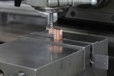
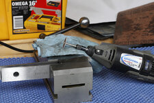
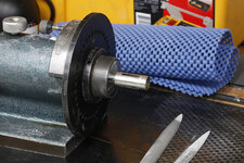
Picture 1: Machining a pure copper electrode that is 2mm x 19mm. It will be used to make 3 symmetrical rectangular holes in the cap. The electrode has a fatter "shank" for clamping in a holder I had to make. In contrast to using round stock for the barrel squares, I'm using an old copper bus bar for this material.
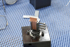
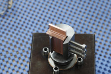
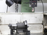
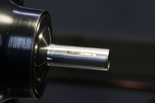
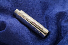
Pictures 2 and 3: showing a couple views of the copper electrode mounted in its holder which in turn is set (but not aligned yet) in a special holder that will attach to the EDM quill.
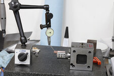
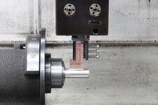
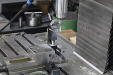
Picture 4: shows the setup for making sure the electrode is square with the special holder. The holder I made that clamps the copper electrode has a 20mm shank that fits into the cubical block. I did not make the cube.
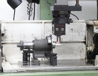
Pictures 5 and 6: shows the setup with the spin indexer holding my silver cap and the EDM quill with electrode sticking down.
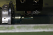
Picture 7: shows the actual alignment for making the 2 x 19 rectangular holes in the cap.
Picture 8: If you look closely you can see the sparks between the electrode and the cap. It's the sparks that slowly erode the silver cap to the shape of the electrode. The hwole thing is submerged in that dielectric fluid to enable sparking. There is a little wear to the electrode so after making the initial hole, the electrode is dressed to get rid of the now rounded edges and the process is repeated with all fresh edges. That "finishes" the holes so the inside corners are as square as they can be and so that the hole is not tapered in depth.
For those that care the parameters are: 100V potential, the current at about 6A is pulsed DC, the electrode is positive, pulse width is about 50µs, my guess at duty cycle is about 25%.
Picture 9: Back to some basics - Using a dremel tool to slice off little rectangles of pearl (the black-lip variety). I sliced off three of these - one for each of the three rectangular holes I made in the cap. I really need to find a better way to slice pearl as this was all hand held and fraught with the potential for error.
Picture 10: I'm using a little vise clamped in yet another vise to shave off the sides of the little pearl slabs to get the precise width. I'm using a high speed spindle with a high helix 1/4 inch carbide end mill. It's turning at 5000 RPM (really not that high but higher than the regular mill can do by 3000 RPM. I had to get this fixture dialed in so that I could mill straight and parallel and perpendicular to the table.
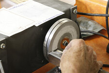
Picture 11: I cobbled together a little fixture to grind the pearl slabs to to correct length. The grinder is a slow speed variety (around 200 RPM) made by GRS with a 240 grit diamond wheel. It didn't need to be diamond but that's what was on there. The picture actually shos me grinding the thickness of the slabs so that as much of the "black" more colorful part of each piece of pearl would show when installed in the barrel. I'm using a toothpick to push the slabs to get the thickness down to about a millimeter. The depth of the holes in the silver cap will be a few thousandths greater than the wall thickness which is .025 inches. Pretty thin but thick enough.
Picture 12: Rough layout of the slabs in the cap. There's an acrylic insert I made that has the threads in it for screwing the pen together and I slid that in the cap to provide an initial backing for the slabs. I just used the tiniest bit of CA to tack the slabs in place on the outside so that I could take the insert out and do additional tacking without the danger of gluing the insert in place in the wrong position. This was an "order of assembly" plan I had to minimize the potential of a mistake. After the additional tacking I press/glued the insert into the cap using another jig. Now I had a permanent backing for the slabs and I added more CA all around each slab. Capillary action with this really thin CA soaks into the joints.
Picture 13: shows a spin indexer I use to file and sand the high points off the cap. It's the same process as what I did for the main barrel.
Picture 14: Here are all the high points sanded off and ready for the really fine sand paper. For some reason the edges of the slab in this picture do not look straight but they really are.
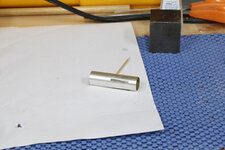
Picture 15: The finished cap with another insert in the top that the cap finial screws on to. All these inserts were made some time ago so I have a small supply of them ready as I make more of this style of pen. Also, you'll see some guilloché (engraving) as a final touch that I put on there after the cap was polished.
Hope this series was interesting. I know it uses techniques and machinery that are uncommon to most folks here but to me it's fascinating and satisfying to put it all together and do thing out of the norm.
Cheers,
Rich
Picture 1: Machining a pure copper electrode that is 2mm x 19mm. It will be used to make 3 symmetrical rectangular holes in the cap. The electrode has a fatter "shank" for clamping in a holder I had to make. In contrast to using round stock for the barrel squares, I'm using an old copper bus bar for this material.
Pictures 2 and 3: showing a couple views of the copper electrode mounted in its holder which in turn is set (but not aligned yet) in a special holder that will attach to the EDM quill.
Picture 4: shows the setup for making sure the electrode is square with the special holder. The holder I made that clamps the copper electrode has a 20mm shank that fits into the cubical block. I did not make the cube.
Pictures 5 and 6: shows the setup with the spin indexer holding my silver cap and the EDM quill with electrode sticking down.
Picture 7: shows the actual alignment for making the 2 x 19 rectangular holes in the cap.
Picture 8: If you look closely you can see the sparks between the electrode and the cap. It's the sparks that slowly erode the silver cap to the shape of the electrode. The hwole thing is submerged in that dielectric fluid to enable sparking. There is a little wear to the electrode so after making the initial hole, the electrode is dressed to get rid of the now rounded edges and the process is repeated with all fresh edges. That "finishes" the holes so the inside corners are as square as they can be and so that the hole is not tapered in depth.
For those that care the parameters are: 100V potential, the current at about 6A is pulsed DC, the electrode is positive, pulse width is about 50µs, my guess at duty cycle is about 25%.
Picture 9: Back to some basics - Using a dremel tool to slice off little rectangles of pearl (the black-lip variety). I sliced off three of these - one for each of the three rectangular holes I made in the cap. I really need to find a better way to slice pearl as this was all hand held and fraught with the potential for error.
Picture 10: I'm using a little vise clamped in yet another vise to shave off the sides of the little pearl slabs to get the precise width. I'm using a high speed spindle with a high helix 1/4 inch carbide end mill. It's turning at 5000 RPM (really not that high but higher than the regular mill can do by 3000 RPM. I had to get this fixture dialed in so that I could mill straight and parallel and perpendicular to the table.
Picture 11: I cobbled together a little fixture to grind the pearl slabs to to correct length. The grinder is a slow speed variety (around 200 RPM) made by GRS with a 240 grit diamond wheel. It didn't need to be diamond but that's what was on there. The picture actually shos me grinding the thickness of the slabs so that as much of the "black" more colorful part of each piece of pearl would show when installed in the barrel. I'm using a toothpick to push the slabs to get the thickness down to about a millimeter. The depth of the holes in the silver cap will be a few thousandths greater than the wall thickness which is .025 inches. Pretty thin but thick enough.
Picture 12: Rough layout of the slabs in the cap. There's an acrylic insert I made that has the threads in it for screwing the pen together and I slid that in the cap to provide an initial backing for the slabs. I just used the tiniest bit of CA to tack the slabs in place on the outside so that I could take the insert out and do additional tacking without the danger of gluing the insert in place in the wrong position. This was an "order of assembly" plan I had to minimize the potential of a mistake. After the additional tacking I press/glued the insert into the cap using another jig. Now I had a permanent backing for the slabs and I added more CA all around each slab. Capillary action with this really thin CA soaks into the joints.
Picture 13: shows a spin indexer I use to file and sand the high points off the cap. It's the same process as what I did for the main barrel.
Picture 14: Here are all the high points sanded off and ready for the really fine sand paper. For some reason the edges of the slab in this picture do not look straight but they really are.
Picture 15: The finished cap with another insert in the top that the cap finial screws on to. All these inserts were made some time ago so I have a small supply of them ready as I make more of this style of pen. Also, you'll see some guilloché (engraving) as a final touch that I put on there after the cap was polished.
Hope this series was interesting. I know it uses techniques and machinery that are uncommon to most folks here but to me it's fascinating and satisfying to put it all together and do thing out of the norm.
Cheers,
Rich
Attachments
-
 11_MG_1008.jpg94.3 KB · Views: 237
 -
 12_MG_1010.jpg177.2 KB · Views: 228
 -
 13_MG_1011.jpg137.7 KB · Views: 202
 -
 14_MG_1014.jpg114.3 KB · Views: 210
 -
 15_MG_1013 rotated.jpg150 KB · Views: 195
 -
 16_MG_1015 rotated.jpg168.5 KB · Views: 188
 -
 17_MG_1017.jpg114.5 KB · Views: 190
 -
 18_MG_1018.jpg78.7 KB · Views: 201
 -
 19_MG_1020.jpg165.4 KB · Views: 180
 -
 20_MG_1024.jpg148.6 KB · Views: 201
 -
 21_MG_1026.jpg116 KB · Views: 210
 -
 22_MG_1028.jpg121 KB · Views: 192
 -
 23_MG_1031.jpg162.6 KB · Views: 179
 -
 24_MG_1033.jpg69.4 KB · Views: 209
 -
 25_MG_1038.jpg187.7 KB · Views: 268