John Den
Member
I thought I would post some more information about my entry for the Exotic Blanks Advanced Pen Competition.
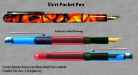
Picture 1
This shows the pen I submitted for the competition. Below this are the images taken off the 3D, TurboCAD drawing. I drew this at the start, to optimise the inside, as well as the outside, dimensions. The Body and Cap were rendered as different coloured glass in order to see what was going on inside.
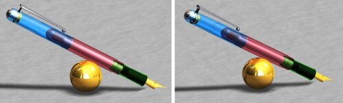
Picture 2
This shows the pen resting on a sphere all totally generated in TurboCAD and gave me an idea on what the finished pen would look like.
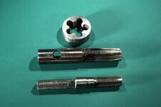
Picture 3
This shows the Taps and Die I made to cut the housing thread in the body and the Cap/Body threads.
The Housing, Feed and Nib, I obtained from Turners Workshop in the UK, came with no technical information at all, so I measured the thread and made the tap. This tap worked well first time (8.3x0.75). It was made out of Drill Rod and hardened and tempered using a butane torch.
Spurred on by this success and the advice I got on this site I deduced that a triple start thread was needed for the body/cap junction. I then started off on what was to be a long road to the three start tap and die, shown in the picture, which actually worked!!! (3 start 12x0.75)
The 3 start tap was machined out of mild steel because its diameter prevented the use of Drill Rod. After machining I then case hardened it (with Case Hardening Powder).This was then used to tap the blank for the die. Because of the 2.25mm lead (0.75x3) it proved very difficult to tap mild steel with this homemade tap. Even starting it on the lathe and then transferring it to my bench vice, I found all my tap wrenches slipped. I reluctantly remade the tap again and cross drilled to take a tommy bar. This worked with a "decent lever length" but it was a bit scary.
The die blank, after tapping, was marked out for 5 holes and drilled on the mill with a slot drill which maintained the hole accuracy even though half the time it was cutting in air. I left the die unhardened as I decided it would only be used on plastic and aluminium for the cap polishing Mandrel.
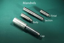
Picture 4
This shows the Mandrels I made and used:-
Regards,
John
Picture 1
This shows the pen I submitted for the competition. Below this are the images taken off the 3D, TurboCAD drawing. I drew this at the start, to optimise the inside, as well as the outside, dimensions. The Body and Cap were rendered as different coloured glass in order to see what was going on inside.
Picture 2
This shows the pen resting on a sphere all totally generated in TurboCAD and gave me an idea on what the finished pen would look like.
Picture 3
This shows the Taps and Die I made to cut the housing thread in the body and the Cap/Body threads.
The Housing, Feed and Nib, I obtained from Turners Workshop in the UK, came with no technical information at all, so I measured the thread and made the tap. This tap worked well first time (8.3x0.75). It was made out of Drill Rod and hardened and tempered using a butane torch.
Spurred on by this success and the advice I got on this site I deduced that a triple start thread was needed for the body/cap junction. I then started off on what was to be a long road to the three start tap and die, shown in the picture, which actually worked!!! (3 start 12x0.75)
The 3 start tap was machined out of mild steel because its diameter prevented the use of Drill Rod. After machining I then case hardened it (with Case Hardening Powder).This was then used to tap the blank for the die. Because of the 2.25mm lead (0.75x3) it proved very difficult to tap mild steel with this homemade tap. Even starting it on the lathe and then transferring it to my bench vice, I found all my tap wrenches slipped. I reluctantly remade the tap again and cross drilled to take a tommy bar. This worked with a "decent lever length" but it was a bit scary.
The die blank, after tapping, was marked out for 5 holes and drilled on the mill with a slot drill which maintained the hole accuracy even though half the time it was cutting in air. I left the die unhardened as I decided it would only be used on plastic and aluminium for the cap polishing Mandrel.
Picture 4
This shows the Mandrels I made and used:-
- The Finial Mandrel was used to turn the hemispherical finial assembled with the stainless steel insert. This worked well and there was no problem at the junction between the acrylic and stainless steel nut insert. The final polishing of the finial and insert was also carried out on this mandrel.
- The Section Mandrel was used to turn the section to its final shape and polish it. I used a lathe tool ground to both the shape of the front and back curve of the section drawing. I then turned it into the section to the depth indicated by my drawing, so that the final shape was made. In between the back and the front curves of the section I cut along making this part cylindrical.
- The Body Mandrel was used to finish the final polishing of the body. The machining had been completed using my ER32 collet system.
- The Cap Mandrel was used, similarly to the Body Mandrel, for polishing the cap.
Regards,
John