Rich L
Member
This post is a long time coming and rather than wait another couple months I hazard to show the half-way done part. My caveat here is that the "fit" is good but the "finish" will improve when I get finished. Getting this far with this new process took months in itself.
I have long been wanting to do some more exotic inlay work and to do that I settled on the EDM process. The reason is that I wanted to create sharp inside corners - sharper than what can be done with even the very smallest end mills. Die sinking EDM is the ticket to this goal. Another possible method would be using a shaper or adapting the slotting head I have for the mill but shaping requires secure workholding (read "clamping") because there is pressure put on the workpiece. I have small and thin pieces I want to work with downstream and and clamping these things down to enable mechanical metal removal could very well be problematic. EDM does not put pressure on the workpiece and it's easier; you just make the electrode and then make the hole. Well, not always quite that easy.
So, to get educated on the process I visited a friend in Texas who has one of the EDM devices - actually he has three - and he taught me to use it and apply that new-found skill to a couple of silver pen barrels I had brought with me. I had already drawn up my prospective design and that included three spirals of square holes in the barrels. The square hole approach was to keep it simple but the shape of a hole capable of being "burned" by a sinker EDM is really only limited to the imagination.
In order to make these holes I needed to make an electrode in the shape I needed - a square. Electrodes can be made from just about conductive material but the common materials are copper, copper-tungsten, and graphite. My teacher eschews graphite so I used some scrap copper-tungsten (WCu) to make my square electrode.
Making EDM electrodes is a challenge in itself because of the accuracy and precision required. It was required that I make a square accurate to ±.0005 of my declared dimension which was a 6mm square (yeah, I'm mixing units). The precision of the milling needed to be about half of that; in other words no excursion while milling. On top of that I needed to make two different sized squares - one for the "roughing" operation which would make my square hole slightly undersized and with slightly rounded corners and then a "finishing" square which would take off a tiny bit more to get my final 6mm dimension and to square up the corners.
Maybe the digression into EDM processes is interesting to some and one can always do the internet tutorial to find out more.
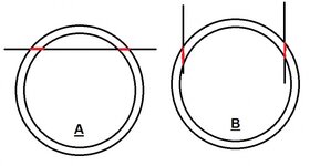
OK, electrodes made so now to burn the holes. I lightly clamped the barrel in a dividing head and set that up in the EDM tank so that the electrode would meet it at the right angle. The dividing head was used to get the spirals evenly spaced aroung the circumference. Actually a simple spin indexer would have been easier to deal with. Each hole took about 15 minutes to do.
Barrels made - returned back home from Texas. Now I need to make the square inlays and I did that out of my current favorite inly material: mother of pearl (MOP). I got three colors of that from knifehandles.com - white, black-lip, and gold-lip. I used a tool and cutter grinder to cut rough squares and I used a different version of the same to grind them precisely to size. I had to make a special tool to hold each square so that the grind would be square on all three axes. he tool shown has a precise 5mm square recess to hold the rough MOP square and you can see the spring used to hold it down. By the way, I fashioned the spring out of a scrap piece of 1095 steel that I had to initially anneal, then shape, then heat to critical temp, quench, and finally temper to spring hardness.
Most of the MOP pieces were too thick so you can see the manual method of thinning them down using my finger to hold them agains a slow spinning flat sanding wheel. Each piece was then fit into one of the holes in the barrel, glued in, and then the high parts were filed and sanded off to be flush with the silver surface. Another tool I had to make was a mandrel that would just slip inside the barrel that had a surface to prevent the MOP squares from just falling through.
All in a day's work")
I have the second barrel to finish and then for the next project, since my feet are nice and wet, I'll be doing some more complex designs.
The next half of this pen - the cap and the clip will follow in a subsequent post and the objective will be to inlay 3mm squares in the clip. The holes, or recesses, will be blind, unlike the holes in the barrel and I've already made some trials. I'll also be embellishing the section with some square-like design but that won't be an EDM thing.
Cheers,
Rich
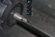
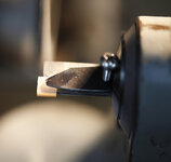
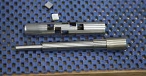
Pic 1: machining the WCu electrode
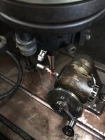
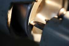
Pic 2: "sinking" the square holes. Typically EDM work is done submerged in a dielectric fluid (oil) but for fun and picture taking this setup just kept a flood of the fluid going so the spark erosion could happen.
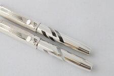
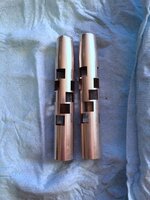
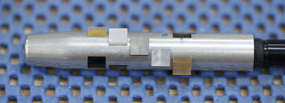
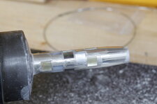
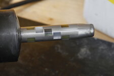
Pic 3: the two barrels with nice square holes in them
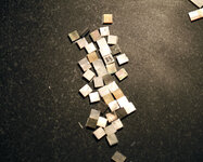
Pic 4: a bunch of rough square MOP pieces
Pic 5: the MOP square special custom holder tool
Pic 6: using a diamond wheel on a tool and cutter grinder to square and size up the MOP squares. Too many "squares."
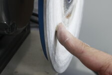
Pic 7: "finger" grinding to thin the MOP squares
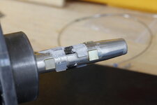
Pic 8: Mandrel used to position (for depth) the squares in the holes
Pic 9: trial layout
Pic 10: all glued in
Pic 11: filing off high points
Pic 12: finish sanding
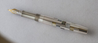
Pic 13: assembled barrel
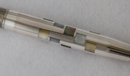
Pic 14: a closeup
I have long been wanting to do some more exotic inlay work and to do that I settled on the EDM process. The reason is that I wanted to create sharp inside corners - sharper than what can be done with even the very smallest end mills. Die sinking EDM is the ticket to this goal. Another possible method would be using a shaper or adapting the slotting head I have for the mill but shaping requires secure workholding (read "clamping") because there is pressure put on the workpiece. I have small and thin pieces I want to work with downstream and and clamping these things down to enable mechanical metal removal could very well be problematic. EDM does not put pressure on the workpiece and it's easier; you just make the electrode and then make the hole. Well, not always quite that easy.
So, to get educated on the process I visited a friend in Texas who has one of the EDM devices - actually he has three - and he taught me to use it and apply that new-found skill to a couple of silver pen barrels I had brought with me. I had already drawn up my prospective design and that included three spirals of square holes in the barrels. The square hole approach was to keep it simple but the shape of a hole capable of being "burned" by a sinker EDM is really only limited to the imagination.
In order to make these holes I needed to make an electrode in the shape I needed - a square. Electrodes can be made from just about conductive material but the common materials are copper, copper-tungsten, and graphite. My teacher eschews graphite so I used some scrap copper-tungsten (WCu) to make my square electrode.
Making EDM electrodes is a challenge in itself because of the accuracy and precision required. It was required that I make a square accurate to ±.0005 of my declared dimension which was a 6mm square (yeah, I'm mixing units). The precision of the milling needed to be about half of that; in other words no excursion while milling. On top of that I needed to make two different sized squares - one for the "roughing" operation which would make my square hole slightly undersized and with slightly rounded corners and then a "finishing" square which would take off a tiny bit more to get my final 6mm dimension and to square up the corners.
Maybe the digression into EDM processes is interesting to some and one can always do the internet tutorial to find out more.
OK, electrodes made so now to burn the holes. I lightly clamped the barrel in a dividing head and set that up in the EDM tank so that the electrode would meet it at the right angle. The dividing head was used to get the spirals evenly spaced aroung the circumference. Actually a simple spin indexer would have been easier to deal with. Each hole took about 15 minutes to do.
Barrels made - returned back home from Texas. Now I need to make the square inlays and I did that out of my current favorite inly material: mother of pearl (MOP). I got three colors of that from knifehandles.com - white, black-lip, and gold-lip. I used a tool and cutter grinder to cut rough squares and I used a different version of the same to grind them precisely to size. I had to make a special tool to hold each square so that the grind would be square on all three axes. he tool shown has a precise 5mm square recess to hold the rough MOP square and you can see the spring used to hold it down. By the way, I fashioned the spring out of a scrap piece of 1095 steel that I had to initially anneal, then shape, then heat to critical temp, quench, and finally temper to spring hardness.
Most of the MOP pieces were too thick so you can see the manual method of thinning them down using my finger to hold them agains a slow spinning flat sanding wheel. Each piece was then fit into one of the holes in the barrel, glued in, and then the high parts were filed and sanded off to be flush with the silver surface. Another tool I had to make was a mandrel that would just slip inside the barrel that had a surface to prevent the MOP squares from just falling through.
All in a day's work
I have the second barrel to finish and then for the next project, since my feet are nice and wet, I'll be doing some more complex designs.
The next half of this pen - the cap and the clip will follow in a subsequent post and the objective will be to inlay 3mm squares in the clip. The holes, or recesses, will be blind, unlike the holes in the barrel and I've already made some trials. I'll also be embellishing the section with some square-like design but that won't be an EDM thing.
Cheers,
Rich
Pic 1: machining the WCu electrode
Pic 2: "sinking" the square holes. Typically EDM work is done submerged in a dielectric fluid (oil) but for fun and picture taking this setup just kept a flood of the fluid going so the spark erosion could happen.
Pic 3: the two barrels with nice square holes in them
Pic 4: a bunch of rough square MOP pieces
Pic 5: the MOP square special custom holder tool
Pic 6: using a diamond wheel on a tool and cutter grinder to square and size up the MOP squares. Too many "squares."
Pic 7: "finger" grinding to thin the MOP squares
Pic 8: Mandrel used to position (for depth) the squares in the holes
Pic 9: trial layout
Pic 10: all glued in
Pic 11: filing off high points
Pic 12: finish sanding
Pic 13: assembled barrel
Pic 14: a closeup
Attachments
-
 1 making electrode 10by.jpg123.1 KB · Views: 359
 -
 2 making squares 10by.jpg164.3 KB · Views: 385
 -
 3 EDM square 10by.jpg126.2 KB · Views: 413
 -
 4 MOP squares 10by.jpg168.5 KB · Views: 311
 -
 5 square holder 8by.jpg70.4 KB · Views: 287
 -
 6 diamond wheel 10by.jpg61.7 KB · Views: 271
 -
 7 thickness grinding 10by.jpg85.1 KB · Views: 236
 -
 8 mandrel 10by.jpg118 KB · Views: 298
 -
 9 trial fit 10by.jpg66.4 KB · Views: 291
 -
 91 ugly fit and file 10by.jpg93.3 KB · Views: 266
 -
 92 less ugly 10by.jpg114 KB · Views: 309
 -
 93 mostly filed off 10by.jpg87.5 KB · Views: 241
 -
 94 bottom half.jpg78.8 KB · Views: 355
 -
 95 bottom half mag 2.jpg145.5 KB · Views: 483