I am joining the CNC world! My CNC router build

Signed-In Members Don't See This Ad
See more from MesquiteMan

MesquiteMan

Retired Head Moderator
Joined
Oct 18, 2005
Messages
5,678
Location
San Marcos, TX, USA.
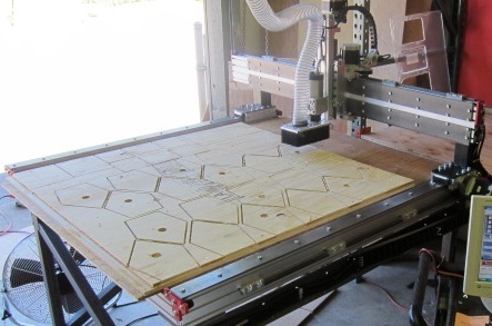
I have decided to bite the bullet and get a CNC router to help increase production on the vacuum chambers I build and reduce my lead times. Needing a 4'x4' cutting area, I started looking at my options and just could not justify $13,000 for a ready made, plug and play machine. After researching the topic thoroughly, I decided to buy a kit from CNCrouterparts.com. When it is all said and done, I will have about $6k in the machine including a $600 copy of Vectric VCarve Pro CAM software and $150 for Mach3 machine control software.

It is common on CNC forums to post a "build" thread so I have one at Sawmill Creek and at CNC Zone and thought it may be something my IAP friends might find interesting. This will be basically a copy and paste from Sawmill Creek.

I have ordered and am assembling a CNC Router Parts CRP4848 machine. I decided to build my own base out of wood instead of using their steel legs since I wanted more weight and read that a lot of folks prefer wood for its dampening abilities. Being that I was a custom home builder for 18 years, I have a lot of experience with LVL (laminate veneer lumber) and know how strong and stable it is so I choose that for my material. I started with 1.75" x 14" LVLs and jointed and planed them to get them straight and smooth. I then ripped them in half, roughly 6.75" once dressed. The legs are 3 pieces glued up to make a roughly 5"x5".

Anyway, here are some pics of my progress thus far:

Day one:

LVL leg glue up

legglueup.jpg

A pile of legs ready to go

Legs.jpg

Base frame glued, nailed, and squared up

Base1.jpg

Legs installed and another set of LVL's inside. I know I do not need them for strength since LVLs are plenty strong but I wanted them to lock in the legs and provide extra weight. The clamp goes to some waste block I screws on to the outside to precisely true it up square. By tightening or loosening the clamp just a little, I can change the squareness.

Corner.jpg

Results at the end of day 1

Day1.jpg
 
Signed-In Members Don't See This Ad

MesquiteMan

Retired Head Moderator
Joined
Oct 18, 2005
Messages
5,678
Location
San Marcos, TX, USA.
Here are the pics from day 2. I went to Lowes to try to find leg levelers but they only had cheap ones for furniture so I decided to make my own.

To make the levelers, I cut some 1.5" x 1/8" steel flat bar about 3" long. I then drilled a 1/2" hole in the center and 4 holes on the outside. I then welded a 1/2" bolt to the back side. Don't laugh at my welding! It is strong but not pretty! It is hidden in the leg anyway.

levelers1.jpg

For the leg itself, I used a 1/2" x 1.5" bolt and welded a large washer to it.

levelers2.jpg

I wanted to make sure the washer was 90° to the bolt itself. I don't have a metal lathe so I chucked them in my drill press and used a piece of MDF with some 120 grit sandpaper glued on and used that to face the washer. I then glued on some rubber washers I found at Lowes onto the nut to provide some vibration dampening and anti-skid. The extra nut it to be able to lock it in place once adjusted.

levelers3.jpg

All of this got painted to prevent rust. I then drilled a 1 1/4" hole about 3/4" in deep in the legs with a forstner bit to provide clearance for the nut and my sloppy welding! I then drilled a 5/8" diameter hole an additional 1.5" deep to provide clearance for the bolt shaft when fully inserted. After all the drilling was done, it was simply attach the levelers with some 1 1/4" truss head screws.

levelerclose.jpg

After the levelers were in, I ran some bottom "joists" for the bottom shelf while I still had it upside down. I started with 2x6's and after planing and jointing to get them straight, they ended up being 1 5/8" x 4" so not much more than a 2x4! If I had started with a 2x4 though, I would have ended up smaller than I wanted.

bottom.jpg

After gluing and screwing all the joists in place, I cheated and used my electric hoist I concocted a few years ago to flip it back over. That thing has come in real handy on many occasions!

flip.jpg

After flipping and moving back to close to where the machine will go, I leveled it all up (did I say how well my homemade levelers worked (
wink.gif
), I installed some 3/4" BC plywood with glue and 2" finish nails for the bottom shelf. At this point, it was close to 2 am so I knocked off for the night!

basefinished.jpg

Thanks for looking and sorry if there was too much boring detail!
 

MesquiteMan

Retired Head Moderator
Joined
Oct 18, 2005
Messages
5,678
Location
San Marcos, TX, USA.
I am sure you guys are getting bored with base pics but I am going to give them to you anyway! I installed the "joists", the MDF top, and the plywood skin to the top section. I believe I am going to wait on the lower skin until after I decide how I am going to use the space underneath. That will be easier once I have my machine and know what I am dealing with as far as electronics, etc. I plan to put the controller and other electronics underneath and may even put the computer box there. Not having any idea what the heck I am doing without parts, I think it will be prudent to wait and see how big of doors or drawers I need to build. I plan to paint the top and skin tomorrow and get ready to start the machine build, hopefully this weekend!

Anyway, here are the progress pics from Thursday night.

Here it is after I installed the joists. I used pocket screws on each end with glue. These are also LVLs. They look funny because I planed them down to get them nice and even and straight. In some cases, I planed through the outer veneer and the black areas are the glue layers.

Joists.jpg

Here it is with the MDF installed. I ran a generous bead of Titebond2 along each framing member and the nailed it ever 6" or so with 2" finish nails. I was going to use screws but decided nailing would be easier. Besides, I just had to keep it in place until the glue dried since glue is stronger than the wood itself anyway! It is perfectly square verified by measuring the diagonals.

Beforeskin.jpg

And here are a couple of shots after I put the skin on the top band. I used 1/2" plywood and plenty of Titebond 2. I ripped the ply about 1/6" oversize and flushed it to the bottom. I nailed it all on with 1 3/8" 23 gauge pin nails. Again, all it has to do is hold it there until the glue dries. After it was nailed up, I used a flush trim bit in my trim router to trim the top of the ply perfectly flush with the MDF.

Endday3-2.jpg

Endday3.jpg

Again, thanks for looking!
 

MesquiteMan

Retired Head Moderator
Joined
Oct 18, 2005
Messages
5,678
Location
San Marcos, TX, USA.
Friday afternoon I had a couple of college kids helping me clean out a spot in the shop for the machine and get ready for the assembly. The spot where I am putting it is where I was storing a few thousand pounds of different burls and logs I have harvested so all of that had to get moved and re-stacked! Then of course everything had to be swept and vacuumed. That was quite a undertaking itself but thankfully, I had 2 strong guys and did not have to lift a finger!

The base was moved into place and leveled up and ready to go. The UPS truck showed up at his normal time of 5:20 or so and we unloaded the parts. Man, were some of them heavy! Here is $4,000 worth of parts ready to unpack and start assembly! Kinda shocking, actually, that these few boxes cost $4k and will be used to make a precision robot!

Parts.jpg

Last night I worked on unpacking the parts and getting them spread out, ready to build. Today I will be spending the day putting stuff together!
 
Last edited:

skiprat

Passed Away Mar 22, 2022
In Memoriam
Joined
Oct 19, 2006
Messages
7,812
Location
In a Skip in Wales
Very impressive and sturdy looking base. I reckon at the speed you are progressing, you'll be in full CNC production by this time tomorrow!!! :eek:

I would have thought that it might be a bit taller so you could get a more user friendly storage area underneath. What made you chose that table height?
 

cnccutter

Member
Joined
Feb 18, 2010
Messages
356
Location
Dorena, Oregon, 97434, USA
go Curtis go

once your up and running you'll find your self doing all sorts of thing you cant imagine right now. when I got mine I only had a few things in mind for it, now I'm booked out 6 weeks doing small custom stuff the big shops don't want to do. the learning curve will come when the router bit hits the table :biggrin:

I cant image not having cnc capability's to add to my hand skills.

Erik
 

MesquiteMan

Retired Head Moderator
Joined
Oct 18, 2005
Messages
5,678
Location
San Marcos, TX, USA.
Skiprat, I thought about going taller but I looked at the spoilboard height of a number of different commercial CNC routers and made it so mine will finish at the same height. I work mostly with 4'x4' acrylic sheets and a 4x4 piece of 1/2 acrylic weighs a LOT! The top of my spoilboard will be proximately 34" off the floor when complete and I figured that is high enough to have to wrangle a piece of heavy material onto by myself!
 

Gregf

Member
Joined
May 22, 2010
Messages
603
Location
Richwood, OH
I've watched a few build threads. Always fun to watch things progress. Make a video of the startup and initial tests.
I've been tempted to make a desktop sized unit. Still convincing myself I need one.
 

MesquiteMan

Retired Head Moderator
Joined
Oct 18, 2005
Messages
5,678
Location
San Marcos, TX, USA.
Congratulations on the new baby! Have you started thinking about dust / noise control yet?

Ed

Yes, I already have that planned! I am looking for a used HF type DC. All I want is the blower and motor and will be venting outside. I plan to build a "shed" outside that the dust and chips will blow in to. I plan to build it wide enough that I can open some doors and use my bobcat to remove the chips when ready! I don't want to mess with bags and such.

I have a Clearvue Cyclone for the main shop area but don't want to run it over to this machine. My shop is a 40x75' metal building. 25x40 on one end is walled off an air conditioned for my main wood shop. The router is going in the other part of the shop so noise will not be a problem since I will have an insulated wall between where I work most and the machine.
 

MesquiteMan

Retired Head Moderator
Joined
Oct 18, 2005
Messages
5,678
Location
San Marcos, TX, USA.
Ah !! 34 inches is good. It guess it just doesn't look as tall as that because it's such a big and chunky size.

The table itself is currently 29.25" to the top. The aluminum extrusions for the cross members are 4" tall which brings it to 33.25". Then I will add a 3/4" MDF spoilboard to that to bring the finished spoilboard height to 34". The top band of my base is 7.25" which makes it look short!
 

Haynie

Member
Joined
May 20, 2011
Messages
3,516
Location
Page Arizona
The best part of this thread is the fact that your business is doing well enough to justify the new toy.

I have been considering one for some of my metal work. What I want to do is far too detailed for me to do with just my hand.
 

longbeard

Member
Joined
Jan 26, 2012
Messages
2,700
Location
West Virginia
Hey Curtis, how many nails did you bend trying to drive them in that stuff?
Hard as a rock and strong enough to drive a tank on. I know, where i work, we make it.
I use drywall screws when i use it.
Congrats on the new toy. Thanks for sharing.
 

ironman123

Member
Joined
Dec 8, 2011
Messages
1,817
Location
Central Texas
I am joining the CNC world! My CNC router build

Congradulations Curtis. This will really speed up your production time on the Acrylic cutting. Mach3 and Mach2 are great programs to use and I know Vectric is very reputable.

Once you get every thing set up, installed and tweaked and the proper G-code running, just watch it do it's magic. Then you might get mad because you waited so long to do it.

Maybe this will make my chamber parts.:biggrin::biggrin:

Good going Curtis.

Ray
 

Curly

Member
Joined
Nov 20, 2010
Messages
4,849
Location
Saskatoon SK., Canada.
Skiprat, I work mostly with 4'x4' acrylic sheets and a 4x4 piece of 1/2 acrylic weighs a LOT! ......... I figured that is high enough to have to wrangle a piece of heavy material onto by myself!

A vacuum lifter and your little electric crane will do the work perfectly and save your back. Basically a big suction cup on a hook. :biggrin: You of all here should be able to rig one up. :wink: For some ideas check out Anver.
 

BRobbins629

Passed Away Dec 28, 2021
In Memoriam
Joined
Mar 8, 2006
Messages
4,037
Location
Richmond, VA, USA.
Looking great Curtis. They are a lot of fun and one of the few tools that you can make parts and take a nap at the same time.
 

MesquiteMan

Retired Head Moderator
Joined
Oct 18, 2005
Messages
5,678
Location
San Marcos, TX, USA.
Skiprat, I work mostly with 4'x4' acrylic sheets and a 4x4 piece of 1/2 acrylic weighs a LOT! ......... I figured that is high enough to have to wrangle a piece of heavy material onto by myself!

A vacuum lifter and your little electric crane will do the work perfectly and save your back. Basically a big suction cup on a hook. :biggrin: You of all here should be able to rig one up. :wink: For some ideas check out Anver.

Great idea....but, my "crane" is at the other end of the shop and is fixed in place. It is not in a good location for putting the CNC machine. I put it down by the main drive in overhead door to make it easy to load and unload things from the truck such as large burls :)

A 4x4 sheet of 1/2" is not too bad. It only weighs 46.5 pounds but is bulky and hard to handle. My acrylic supplier will cut a 4x8 sheet in half for me at no additional cost to make 2 4x4 sheets so I have them do that. That is the main reason I am not building a 4x8 machine. A 4x8 sheet of 1/2" acrylic weighs nearly 100 pounds. That and the fact it is not in my budget and I don't want to tie up that much shop space!
 

MesquiteMan

Retired Head Moderator
Joined
Oct 18, 2005
Messages
5,678
Location
San Marcos, TX, USA.
Looking Great Curtis!
Maybe I'll get my present order faster now that you are CNC'ing.
I'm owner of CNC Shark Pro and love it.

ABSOLUTELY, sir! That is the plan! Right now, it takes me 4-5 hoursto cut and route parts for 13 pen chambers. According to the time estimate in VCarve Pro, it will take the machine 1:18 to cut the same parts with better accuracy than I can do by hand which will make the assembly go together smoother as well. Then on to the lids. Right now, it take an average of 1 hour for each lid. I am going to change my lid design and now make them out of another material where I can do it all on the CNC. The software says it will take 2:23 to cut the parts, chamfer the edges, drill the holes, and v-carve my logo in the top. Of course there will be tool change time in there but even if it takes 3 hours+, that is for 26 lids that would have taken 26 hours by hand!

I should have done this a long time ago but I am in a position where I am debt free and trying to stay that way. I was going to do this last year but would have had to borrow money to do it and just did not want the debt. Instead, I waited a year and was able to pay cash.
 

MesquiteMan

Retired Head Moderator
Joined
Oct 18, 2005
Messages
5,678
Location
San Marcos, TX, USA.
OK, here is where I am today thus far. I had to take a break since it is so hot in the shop! I am not used to working in the non air conditioned portion of my shop!

I wanted a good way to attach the base of the machine to my wood base and did not want to just use angles attached to the inside of the frame down to the wood. My wood frame is too deep to drill all the way through so since the machine frame is extrusion, I decided to use the bottom t slot with an old stair maker's trick for attaching newel posts. I drilled a hole down from the top where the center of the t track is the correct diameter for a bolt plus a little play. I then drilled a 1 3/8" diameter hole in the side a couple of inches down to intersect the bolt hole. This will be a clearance hole to put the washer and nut and get a wrench in there to tighten it all down.

holddown1.jpg

holddown2.jpg

I did not have any special headed t-bolts so I did a little playing and found I could take a regular 1/4-20 bolt and weld some spots on opposites sides and that would keep if from spinning inside the extrusion and allow me to tighten it all down.

tbolt.jpg

tbolts.jpg

Here is a pic of the side of the table with all the holes. After I get the machine all together, I will run a piece of trim to cover the holes and probably paint it a different color to provide an accent.

holddown4.jpg

Here is a pic of the top with the bolts installed before installing the extrusion.

tablewithholddowns.jpg

This is how the bolt interfaces with the extrusion. Kinda hard to see since it was hard to photograph.

holddown3.jpg

And here it is with the outside frame installed. The interior cross pieces are just sitting in place in this pic. I am working on fastening them now.

frame.jpg
 

Ed McDonnell

Member
Joined
Oct 20, 2008
Messages
2,294
Location
Melbourne, FL
Hi Curtis - Until you get some cuts under your belt to see how your machine performs on real world cuts I wouldn't put too much faith in the cut times estimates you are seeing in VCarve. You will likely need to set a scaling factor in VCarve to get more realistic estimates of cut time.

Given your production focus, you will also likely want to manually fine tune your G-Code to get optimal performance. The code VCarve generates is pretty good, but it can often be improved for production jobs.

Have you considered how much the aluminum might move vs the wood base as the seasons change? I was surprised to see you bolting the aluminum machine to the wood base.

Ed
 

teamtexas

Member
Joined
Apr 24, 2013
Messages
147
Location
Gatesville, Texas
Curtis, have you accounted for the need to level the aluminum extrusion. When I built my gantry cnc mill I sure wish I would have figured in a way to tweak the frame to account for a less the perfect base. Shims would work, but some type of screw leveling would be better.
What type of linear bearings did the kit come with?
Dan
 

MesquiteMan

Retired Head Moderator
Joined
Oct 18, 2005
Messages
5,678
Location
San Marcos, TX, USA.
Ed, see notes below in red

Hi Curtis - Until you get some cuts under your belt to see how your machine performs on real world cuts I wouldn't put too much faith in the cut times estimates you are seeing in VCarve. You will likely need to set a scaling factor in VCarve to get more realistic estimates of cut time.

I have already set my feed rates considerably lower than I should be able to get with the tooling I am using in acrylic. I set it about half of what I should be able to run. VCarve Pro takes this into consideration when estimating the time. I really don't care, however. Even if it takes twice as long as doing it manually, it will still be faster and much more precise!

Given your production focus, you will also likely want to manually fine tune your G-Code to get optimal performance. The code VCarve generates is pretty good, but it can often be improved for production jobs.

I'll look into that some day in the future. Thanks for the info. Do you have any suggestions for reference materials I should look at? I am not at all interested in learning G-code, though!

Have you considered how much the aluminum might move vs the wood base as the seasons change? I was surprised to see you bolting the aluminum machine to the wood base.

Yes, I have considered this. That is why I am using 100% engineered materials. My structural components are laminated veneer lumber. In my extensive testing and experience of 18 years as a hands on, super picky builder, I have found that LVLs just don't move. I used them extensively in the houses I built and they were subjected to much worse conditions than in a shop. Getting rained on, etc. Besides, aluminum and steel both move also with changes in temperature. I thought of building a steel base but am not a good enough welder to know how to weld to prevent heat warpage!

What would be your suggestion? I do NOT want to just sit it on the base. I went and saw a machine similar to mine that was just sitting on a base and was not impressed with that part of it.


Ed

Thank you very much for your comments, btw!
 
Last edited:

MesquiteMan

Retired Head Moderator
Joined
Oct 18, 2005
Messages
5,678
Location
San Marcos, TX, USA.
Curtis, have you accounted for the need to level the aluminum extrusion. When I built my gantry cnc mill I sure wish I would have figured in a way to tweak the frame to account for a less the perfect base. Shims would work, but some type of screw leveling would be better.
What type of linear bearings did the kit come with?
Dan

I plan to use metal shims as I don't know of a good way to do it otherwise. The good thing is, my base is about as perfect as possible! It is perfectly square and flat and has been leveled with an expensive laser level (not an el chepo home depot special).
 

Ed McDonnell

Member
Joined
Oct 20, 2008
Messages
2,294
Location
Melbourne, FL
Hi Curtis - see comments in green (if I can do it :biggrin:)
Ed, see notes below in red

Hi Curtis - Until you get some cuts under your belt to see how your machine performs on real world cuts I wouldn't put too much faith in the cut times estimates you are seeing in VCarve. You will likely need to set a scaling factor in VCarve to get more realistic estimates of cut time.

I have already set my feed rates considerably lower than I should be able to get with the tooling I am using in acrylic. I set it about half of what I should be able to run. VCarve Pro takes this into consideration when estimating the time. I really don't care, however. Even if it takes twice as long as doing it manually, it will still be faster and much more precise!

The nature of your parts will determine what your actual cut rate is. Your machine will need to decelerate to go around corners. The more square the corner needs to be, the more it decelerates to make the turn. The more corners the more time lost in decel / accel. But you are right, once you have a proven toolpath, you can be doing other things while it runs, so even if it doesn't end up being faster, you will end up being more productive.

Given your production focus, you will also likely want to manually fine tune your G-Code to get optimal performance. The code VCarve generates is pretty good, but it can often be improved for production jobs.

I'll look into that some day in the future. Thanks for the info. Do you have any suggestions for reference materials I should look at? I am not at all interested in learning G-code, though!

You won't need to learn a lot of G-Code. Things like eliminating unnecessary retracts (deleting lines of code) and ordering of cuts (moving blocks of code around) can make a huge difference in time. They will be relatively simple changes when the time comes. You will also find that how you design in VCarve can make a big difference in performance. I moved up to Aspire from VCarve a couple of years ago, but my understanding is that the current version of VCarve is a lot more efficient.

Have you considered how much the aluminum might move vs the wood base as the seasons change? I was surprised to see you bolting the aluminum machine to the wood base.

Yes, I have considered this. That is why I am using 100% engineered materials. My structural components are laminated veneer lumber. In my extensive testing and experience of 18 years as a hands on, super picky builder, I have found that LVLs just don't move. I used them extensively in the houses I built and they were subjected to much worse conditions than in a shop. Getting rained on, etc. Besides, aluminum and steel both move also with changes in temperature. I thought of building a steel base but am not a good enough welder to know how to weld to prevent heat warpage!

I understood the stability of the laminate. It was the aluminum movement I was thinking of. If I did my calcs right (and I might not have) you might get up to a 1/16" movement across 4 feet of aluminum from summer to winter. That's going to show up somewhere if your machine is tightly bolted to the table.

What would be your suggestion? I do NOT want to just sit it on the base. I went and saw a machine similar to mine that was just sitting on a base and was not impressed with that part of it.

I have my CNC just sitting on it's base, although I did make my base bigger than my machine by about 12" on each side. Are you worried about the machine moving? If the machine is tuned right, it will run very smooth. Think about how you would attach a desk top to account for movement. Maybe you might consider securing only one side, or losen / tighten the bolts a couple times a year as the seasons change.

Ed

Thank you very much for your comments, btw!
 

MesquiteMan

Retired Head Moderator
Joined
Oct 18, 2005
Messages
5,678
Location
San Marcos, TX, USA.
Ed,

That makes sense about the aluminum movement! Thanks for that heads up. Since the holes through the wood that the bolts go through are larger than the bolt itself, I wonder if it would allow some movement there. If not, I will take into consideration about loosening the bolts periodically. That is a great idea. What do you have for a a CNC?

As for Aspire vs. V-Carve Pro 7, from my understanding from reading CNC Zone and the Vectric forum, it appears that they are mostly identical in the functions that they share. I currently don't have a need for any of the added features of Aspire and sure as heck don't have the budget right now! All of my production needs are simply rectangles and nothing more. Of course I will use it to play with as well when I am not working doing such things as signs, etc!

One question...I have my parts nested well so that they are very similar to how it would be cut on a tablesaw. In other words, the edges all line up. Would I be better setting toolpaths to make a long cut the length of the sheet rather than cutting each individual part at a time?
 

theidlemind

Member
Joined
Mar 13, 2010
Messages
506
Location
Berea, Kentucky 40403
You are killing me with this thread Curtis (subscribed).
I've got a small cnc router (10x24) built just waiting on funds for the cutter and the software. The software combo you are getting is EXACTLY what I am getting when funds allow.
Great thread!
 
Joined
May 14, 2012
Messages
667
Location
Rapid City,SD
PLEASE do some videos of this in action this will be interesting to see. Keep up the good work.

Levi Woodard
Woodardwoodworks.com

Sent from my Rooted Galaxy Player.
 

joefyffe

Passed Away Aug 19, 2018
In Memoriam
Joined
Mar 29, 2010
Messages
1,316
Location
Indianapolis (almost Zionsville) Indiana
Looking Great Curtis!
Maybe I'll get my present order faster now that you are CNC'ing.
I'm owner of CNC Shark Pro and love it.

ABSOLUTELY, sir! That is the plan! Right now, it takes me 4-5 hoursto cut and route parts for 13 pen chambers. According to the time estimate in VCarve Pro, it will take the machine 1:18 to cut the same parts with better accuracy than I can do by hand which will make the assembly go together smoother as well. Then on to the lids. Right now, it take an average of 1 hour for each lid. I am going to change my lid design and now make them out of another material where I can do it all on the CNC. The software says it will take 2:23 to cut the parts, chamfer the edges, drill the holes, and v-carve my logo in the top. Of course there will be tool change time in there but even if it takes 3 hours+, that is for 26 lids that would have taken 26 hours by hand!

I should have done this a long time ago but I am in a position where I am debt free and trying to stay that way. I was going to do this last year but would have had to borrow money to do it and just did not want the debt. Instead, I waited a year and was able to pay cash.

smart move!
 

teamtexas

Member
Joined
Apr 24, 2013
Messages
147
Location
Gatesville, Texas
Curtis, how are you planning to hold your stock in place while you cut the sheet into parts? Are you going to make a vacuum hold down jig? This may affect how you plan to make the cuts.

Long cuts are a bit easier on the controllers but the geckos should have no problem with cutting one piece at a time or all the pieces at once. I originally was planning on nesting pieces and using a full sheet of abs plastic to cut the dies I sell, but later found it easier rough cut the ABS into blanks and use a common hold down jig to machine them one at a time. It took my process from about 15 minutes a piece to 1.5 min. per piece.
Dan
 
Signed-In Members Don't See This Ad

Ed McDonnell

Member
Joined
Oct 20, 2008
Messages
2,294
Location
Melbourne, FL
One question...I have my parts nested well so that they are very similar to how it would be cut on a tablesaw. In other words, the edges all line up. Would I be better setting toolpaths to make a long cut the length of the sheet rather than cutting each individual part at a time?

My initial answer would be yes. The less you move the z-axis up and down and the less you change direction, the faster the job will complete. This strategy (assuming you are doing only straight cuts on x & Y) would also give you perfectly square corners. When cutting around corners (one part at a time) there is a tradoff between machine speed and corner integrity (aka "rounding"). Sign makers can tolerate a lot more corner rounding than guys who need their parts to fit together.

But it's not a simple question.

Depending on the precision / accuracy of your build you might have to cut each part individually to get to what you need. You won't know this until you see what your machine can do as you build it. I run all leadscrews with CNCRouterpart linear motion components. My error is less than 0.001" across 18" during a job. R&P may have a little more error than that across 4 feet. You'll have to do some test runs.

How you hold your material will make a difference in your optimal machining strategy. With vacuum ($,$$$) you don't want to cut any more opening in your material than necessary. If your job will always be the same, you could make a custom plenum for yourself that would make this less of an issue. Long straight line cuts would be best here.

Given the cost of a large vacuum setup (I don't have one because I had a stroke when I saw the cost), I suspect you might be using clamps / tabs. This is a very affordable and pretty effective way to hold the work, but it does requre a little cleanup work to get rid of all the tabs. On wood, no problem. Your use of acrylic might make this more of a nuisance than you are expecting. Anyway, with tabs, you won't gain as much by using long straight line cuts as you would without the tabs. Probably still better though.

Having said all that, given the cost of your material you will probably want to make minimizing material waste a higher priority than minimizing machine time.

While I'm thinking about it, consider picking up some foam sheets for test runs on your machine. You don't want to waste pricey acrylic getting things dialed in and testing toolpaths.

I think I've wandered off into the woods here......back to your questions.

For what you are doing you don't need Aspire. If you were into 3D rotary carving then it would be a different situation. VCarve is a super program. You will easily be able to produce toolpaths to do what you need. However, getting your machine to produce parts that fit together the way you want is another whole journey fraught with pitfalls. Having a laid back attitude (and not trying to meet tight production deadlines right at the start) will help a lot.

I've got a couple self built machines, but the one I use the most (99%+) is my Digital Ornamental Lathe ("DOL"). I built it using a lot the linear motion components from CNCRouterparts. I didn't use R&P though so I can't help you with that. But if you have any other question I'm happy to answer them (or at least try to think up an answer:wink:).

I'm not a CNC pro by a longshot. I'm just a guy who is a little further up the hill than you and who is willing to share what he's learned from the mistakes he's made.

Good luck.

Ed
 
Top Bottom