YATSDRO

Signed-In Members Don't See This Ad

BigShed

Member
Joined
Feb 14, 2008
Messages
1,068
Location
Adelaide, SA, Australia.
.......Yet Another Tailstock DRO (don't you just love acronyms?
doh.gif


(This is a repeat of a thread I posted back in September last year on Woodwork Forums in Oz, as most of you may not have access to that forum and I posted some pics in a thread here I thought I would repeat the full original thread here)

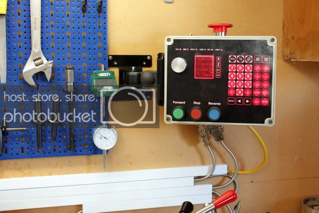
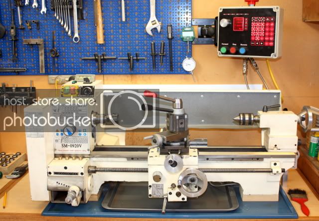
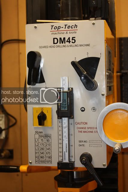
For some time I have been wanting a DRO on the tail stock of my metal lathe, particularly after adding one to the quill of my DM45 mill.

I have been saving various links of how other people have done it and my main inspiration for this one is a thread on HSM.

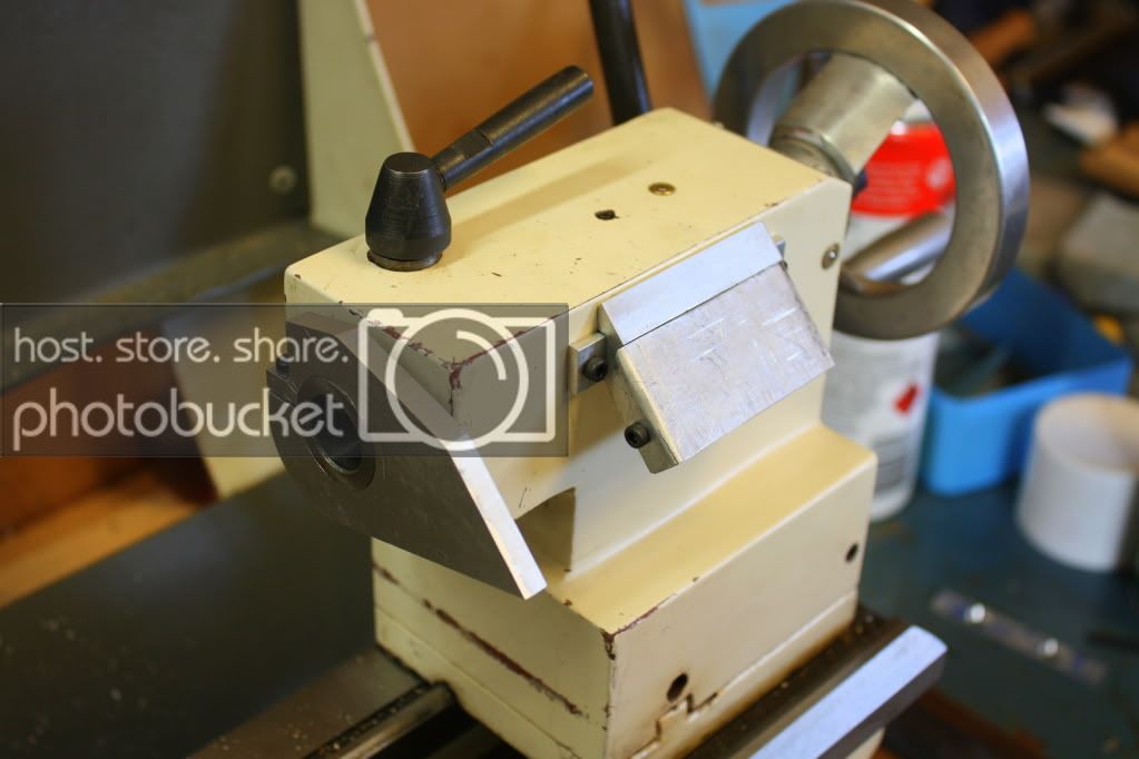
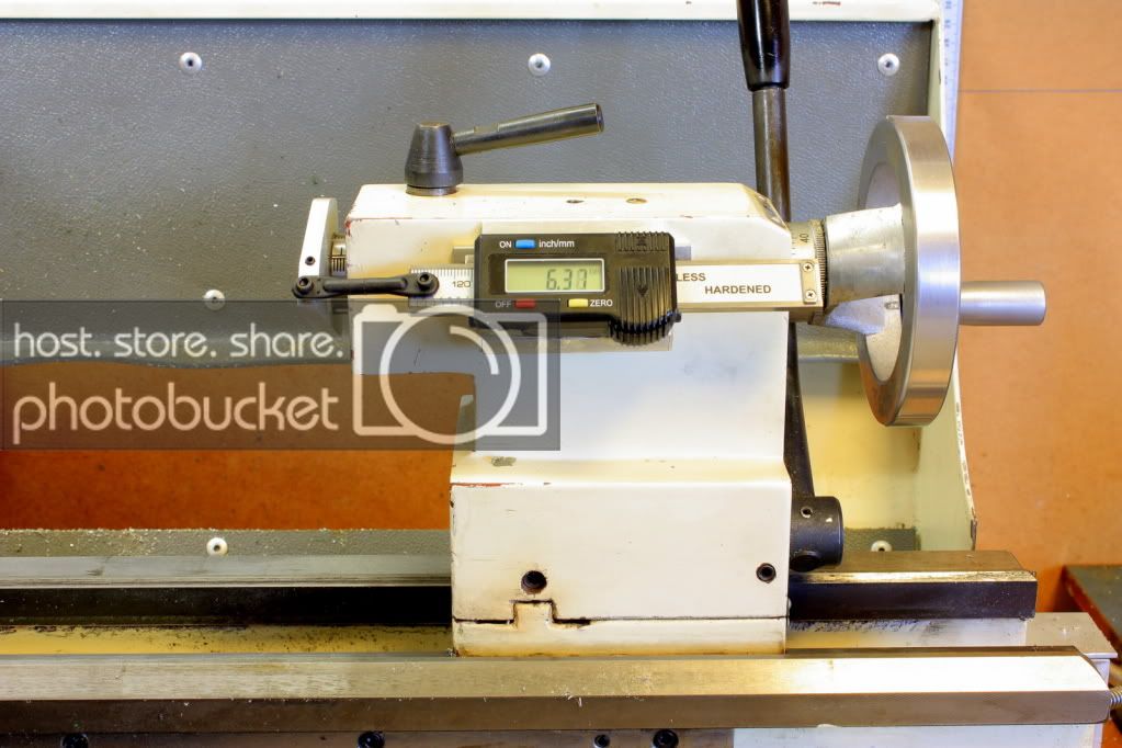
Ideally I would have liked the DRO to flat on top of the tailstock, but this is made impossible by the tailstock locking knob and the oiling point on top.

So I opted to go for the approach in the above link, but used a 45deg angle.

IMG_3162.jpg


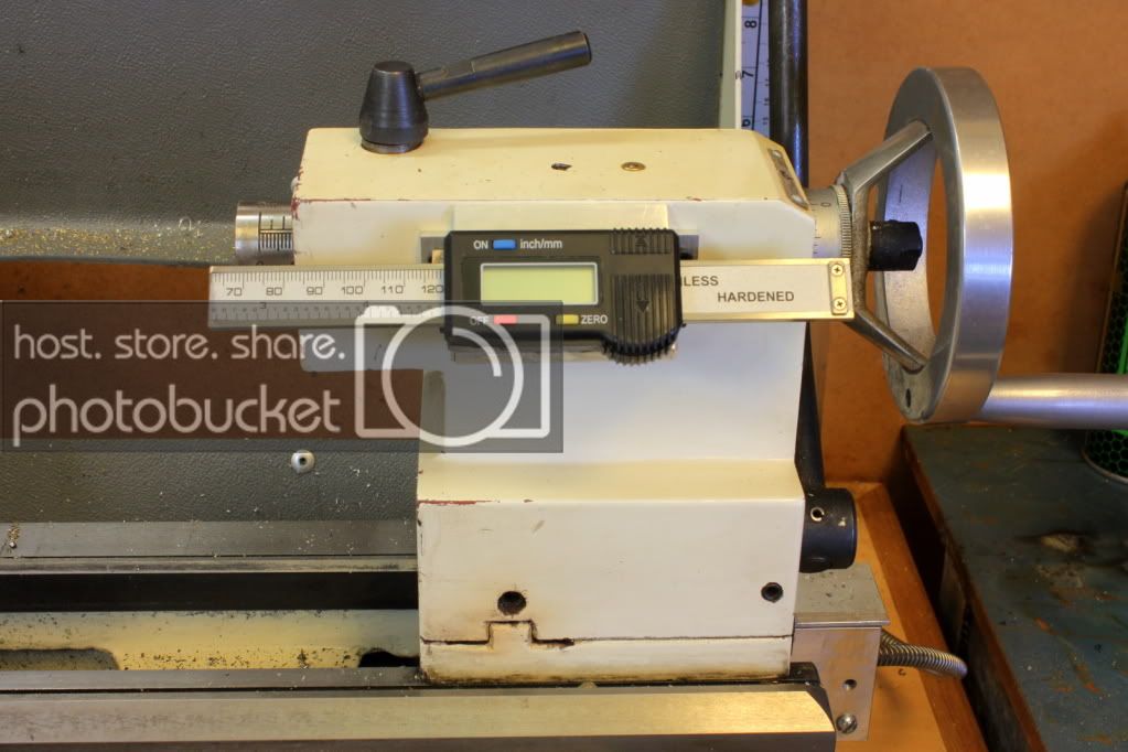
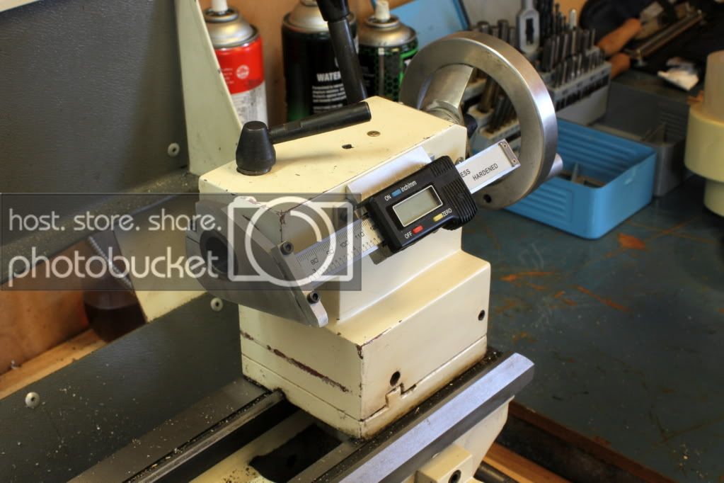
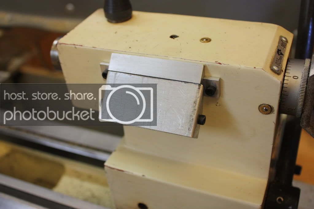
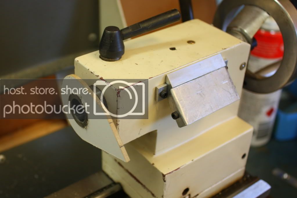
I wanted to be able to remove the DRO easily, so bent up a piece of aluminium to fit on top of the bracket.


Because of the angles involved I opted to make a template out of some 3mm MDF first.


This proved to be an easy approach and gave some precise measurments, time well spent.


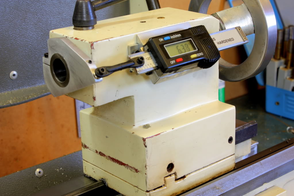
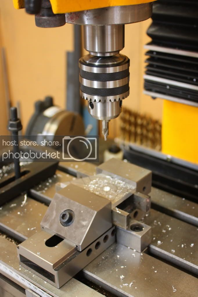
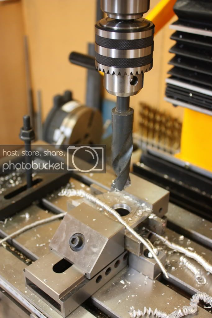
Once the template was made and the pattern transferred to some 6mm aluminium, I could start on making the 26mm hole for the tailstock quill.


Most of the metal was removed with a 7/8" drill, which proved rather quick.


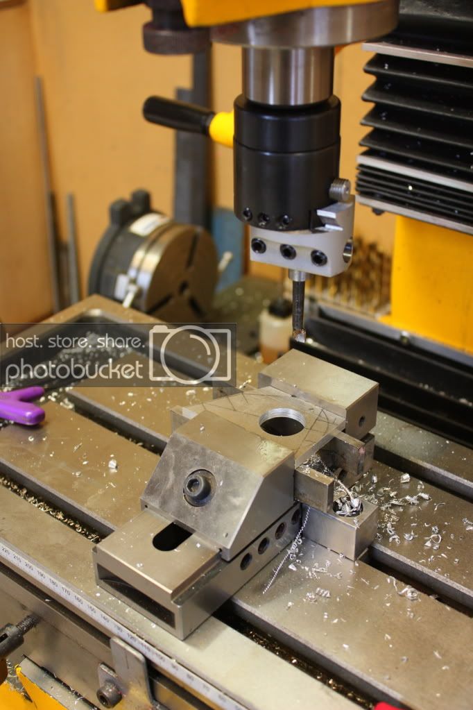
The on to the 2" borng head, first time I had used this tool, and what a great tool this is and so easy to dial precise adjustments to the hole diameter.
2thumbsup.gif


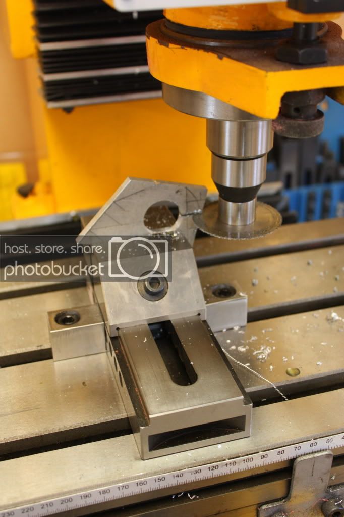
On to the slitting saw to make a clamp section.
 
Last edited:
Signed-In Members Don't See This Ad

BigShed

Member
Joined
Feb 14, 2008
Messages
1,068
Location
Adelaide, SA, Australia.
After cutting away the waste material (on the bandsaw), we finish up with this

IMG_3173.jpg


Attach the DRO to the loose bracket with 2 pack epoxy and attach to the fixed bracket

IMG_3203.jpg


Made up a clamp by milling out a scrap of 6mm aluminium.

After drilling and tapping some holes for M3 socket heads, the monet of truth arrives
2thumbsup.gif


IMG_3200.jpg


Happy to report it all works as expected
2thumbsup.gif
2thumbsup.gif


Would I do anything different if I had to do this again?

Yes, I wouldn't cut the slope on top that goes down to the clamp until I had made and attached the clamp.
doh.gif


But, I can always make another one at some stage, probably when it really starts to annoy me. But it is only cosmetic, doesn't change the way it works.
no.gif
 
Last edited:

BigShed

Member
Joined
Feb 14, 2008
Messages
1,068
Location
Adelaide, SA, Australia.
Whilst the setup shown above worked, it was prone binding because of the rotational force from the tailstock quill.

I had seen another way of connecting the DRO to the front bracket, but wasn't sure about the RC ball links and how they worked.

Went to the local hobby shop and bought a set to try, quite nifty and relatively easy to install.

IMG_3331.jpg


This new setup allowed me to reduce the size of the front bracket as well.

I also shortened the DRO slide a bit further so now it acts as a stop so the tailstock quill doesn't run off the internal thread when I don't think about it, very annoying when that happens when you are drilling and the quill and chuck all of a sudden starts spinning
mad.gif
doh.gif


IMG_3329.jpg

 
Last edited:

BigShed

Member
Joined
Feb 14, 2008
Messages
1,068
Location
Adelaide, SA, Australia.
Fred, I don't have any red X's on mt lathe to attatch anything to:biggrin::confused::confused::confused:

Roy, I think I know what you are saying:confused::confused::confused::biggrin: Photos not showing up for you, is that right????:confused::confused::confused::confused:

Have redone them and you should be able to see them now.

I did a direct copy from WWF, but if you are not a member there they won't show up for you, so re-posted them them direct from Photobucket.

Sorry about that chief, took me a little while to decode your obtuse post:tongue:
 

BigShed

Member
Joined
Feb 14, 2008
Messages
1,068
Location
Adelaide, SA, Australia.
Of course these calipers can be used on other machines as well.

Here is one on the Z axis of my DM45 mill, which has a bit of backlash (yet to be fixed) and this caliper overcomes that nicely.

IMG_2527.jpg
 

bluwolf

Member
Joined
Oct 2, 2008
Messages
995
Location
SW Florida
Fred,

That looks very similar to the caliper I put on my Z of my mill. Do you have DROs on the X and Y of your mill also? I couldn't afford to go the whole glass scale route on the mill. So I put a couple of the cheap ones on there and they work great.

Mike
 

BigShed

Member
Joined
Feb 14, 2008
Messages
1,068
Location
Adelaide, SA, Australia.
Fred,

That looks very similar to the caliper I put on my Z of my mill. Do you have DROs on the X and Y of your mill also? I couldn't afford to go the whole glass scale route on the mill. So I put a couple of the cheap ones on there and they work great.

Mike

Not as this stage Mike, been trying to convince myself to cough up for a 3 axis glass scale DRO system for the mill. This caliper was supposed to be a temporary measure.

The more I see of the LCD cheap scales, the more I becoming convinced that is the way I should go.
 

OKLAHOMAN

Member
Joined
May 17, 2006
Messages
10,228
Location
Costa Rica
Sorry I posted in code:wink: but I knew you'd figure it out:biggrin:thanks for the photos.
Fred, I don't have any red X's on my lathe to attatch anything to:biggrin::confused::confused::confused:

Roy, I think I know what you are saying:confused::confused::confused::biggrin: Photos not showing up for you, is that right????:confused::confused::confused::confused:

Have redone them and you should be able to see them now.

I did a direct copy from WWF, but if you are not a member there they won't show up for you, so re-posted them them direct from Photobucket.

Sorry about that chief, took me a little while to decode your obtuse post:tongue:
 

bluwolf

Member
Joined
Oct 2, 2008
Messages
995
Location
SW Florida
Fred,

That looks very similar to the caliper I put on my Z of my mill. Do you have DROs on the X and Y of your mill also? I couldn't afford to go the whole glass scale route on the mill. So I put a couple of the cheap ones on there and they work great.

Mike

Not as this stage Mike, been trying to convince myself to cough up for a 3 axis glass scale DRO system for the mill. This caliper was supposed to be a temporary measure.

The more I see of the LCD cheap scales, the more I becoming convinced that is the way I should go.

Oh, it's definitely the way to go unless you have a spare $6 or $700 laying around:biggrin:

Mike
 

BigShed

Member
Joined
Feb 14, 2008
Messages
1,068
Location
Adelaide, SA, Australia.
Fred, Nice explanation and good set of photos, I believe I might just give it a try on mine Thanks.

My pleasure, show us some pics when you have it done.

Fred,

That looks very similar to the caliper I put on my Z of my mill. Do you have DROs on the X and Y of your mill also? I couldn't afford to go the whole glass scale route on the mill. So I put a couple of the cheap ones on there and they work great.

Mike

Not as this stage Mike, been trying to convince myself to cough up for a 3 axis glass scale DRO system for the mill. This caliper was supposed to be a temporary measure.

The more I see of the LCD cheap scales, the more I becoming convinced that is the way I should go.

Oh, it's definitely the way to go unless you have a spare $6 or $700 laying around:biggrin:

Mike

No I don't, I'm saving my "play" money for another major addition to the play pen, so will probably get 2 LCD scales as working the mill from the dials is a real pain, particularly as I am used to DROs on the lathe.
 

PenPal

Member
Joined
Nov 29, 2006
Messages
2,708
Location
Canberra, A.C.T., Australia.
Hi Fred,

Well done mate I admire your thinking, clean making approach in all things. I also believe your approach to cutting threads on pens shown also on the forum to be far and away superior to any other demoed so far, so many of us use the die holder but it was pure genius IMHO to utilise that die holder to set a modified tee wrench into that same device for female threads.

I use a DRO on my Pen Device with my Mill, my only problem and you have used a similar level of manufactured DRO is they are under designed in the readout , battery dept. Mine I find hard to keep up with the battery life and the occassional self switching on although I admit mine is designed for vertical reading the letters are smaller.

Please keep on keeping on with your efforts to enlighten those of us on a real budget in our machine shop practices with your efforts much appreciated at all times. Not once have I detected any suggestion of one upsmanship or conceit in fact your humble sharing epitomises sharing.

Kind regards,

Peter.
 
Top Bottom